Icon System Manual T02985_02_03 71
MRI System Operation
Figure 5.7: All connections to the Basic Animal Holder are established.
(1) Warm water tubes; (2) Isofluorane supply; (3) Scavenging; (4) Cable of RF Coil
5.2.4 Connecting RF Coils
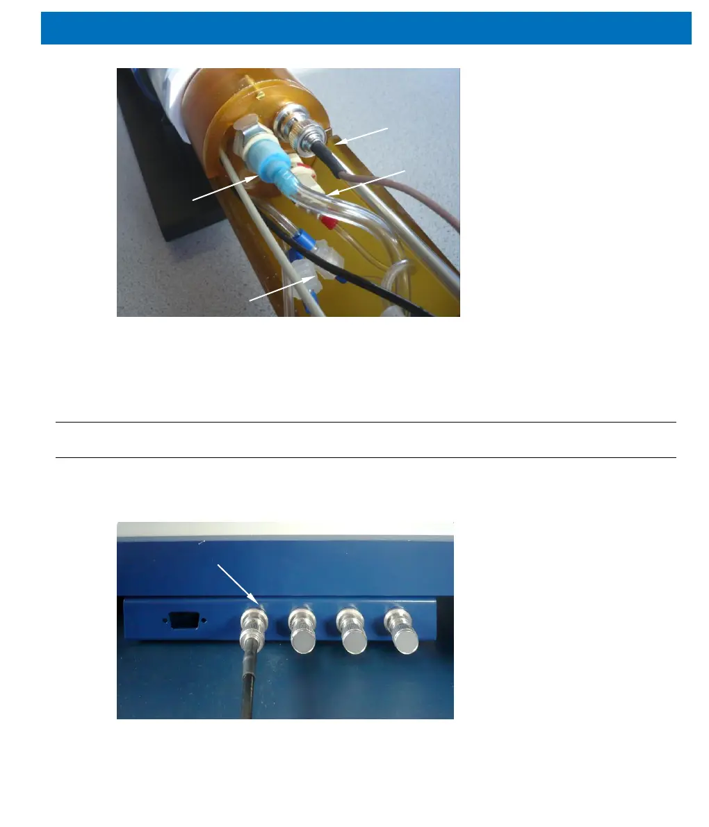
5.2.4.1 Animal Bed mounted RF Coils
The black RF connection cable leading out of the basic holder (labeled “RF Coil”) is
connected to the left-most connection (1) located on the bottom side of the magnet, as
shown in Figure 5.8. The other connections are not in use (not connected).
Figure 5.8: RF Coil connection located on the magnet’s bottom side