BRUNSWICK INSTALLATION MANUAL PAGE 3
CANTON
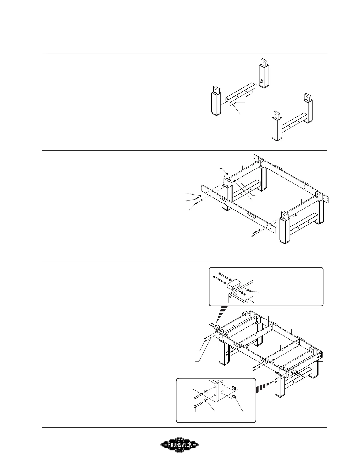
BASEFRAME AND LEG ASSEMBLY
FIGURE ONE
FIGURE ONE
FIGURE TWO
FIGURE TWO
Step #1: Arrange legs into place and connect them
to the end stretchers using 3/8-16 x 1-3/4” hex head
screws and 3/8 washers.
Step #2: Attach the two baseframe side sills “A” to
the legs as shown using 3/8-16 x 3 1/4” hex head
screws, 3/8 washers and 3/8 hex nuts.
3/8-16 x 4-1/2”
HEX HEAD SCREW
3/8 NUT
3/8 WASHER
FIGURE THREE
FIGURE THREE
Step #4: Attach the two baseframe sills “C” to the
side sills as shown using 5/16-18 x 2-1/2” hex head
screws, 5/16 washers and 5/16 at nuts.
5/16-18
FLAT NUT
5/16 FLAT
WASHER
5/16-18 x 2-1/2”
HEX HEAD SCREW
Step #5: Attach the two slate joint support sills “D” as
shown using 5/16-18 x 2-1/2” hex head screws, 5/16 at
washers and 5/16-18 at nuts.
Step #6: Attach the two slate attach cleats to each end of
the baseframe “B” as shown using 5/16-18 x 3-1/2” hex
head screws, 5/16 at washers and 5/16 hex nuts.
A
C
D
5/16 FLAT WASHER
5/16-18 x 3-1/2” HEX HEAD SCREW
5/16 FLAT WASHER
5/16 HEX NUT
A
C
D
5/16-18 x 2-1/2”
HEX HEAD SCREW
3/8-16 x 1-3/4”
HEX HEAD SCREW
3/8 WASHER
A
A
B
B
3/8 WASHER
FLAT NUT
3/8-16 x 3-1/4”
HEX HEAD SCREW
Step #3: Attach leg cross supports “B” between
leg posts using 3/8-16 x 4-1/2” hex head screw,
3/8 washer and 3/8-16 at nut as shown.
5/16 FLAT WASHER