BASEFRAME AND LEG ASSEMBLY
FIGURE FOUR
FIGURE FOUR
FIGURE FIVE
FIGURE FIVE
FIGURE SIX
FIGURE SIX
CANTON
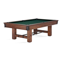
Step #7: Attach the center support sill “E” as shown
using 5/16-18 x 2-1/2” hex head screws, 5/16 at washers
and 5/16-18 at nuts.
Step #8: Position the baseframe assembly so that each
side and end of the baseframe is at least 60 inches from
any wall or partition to achieve adequate playing
clearance.
5/16-18 x 2-1/2”
HEX HEAD SCREW
5/16 WASHER
5/16-18 FLAT NUT
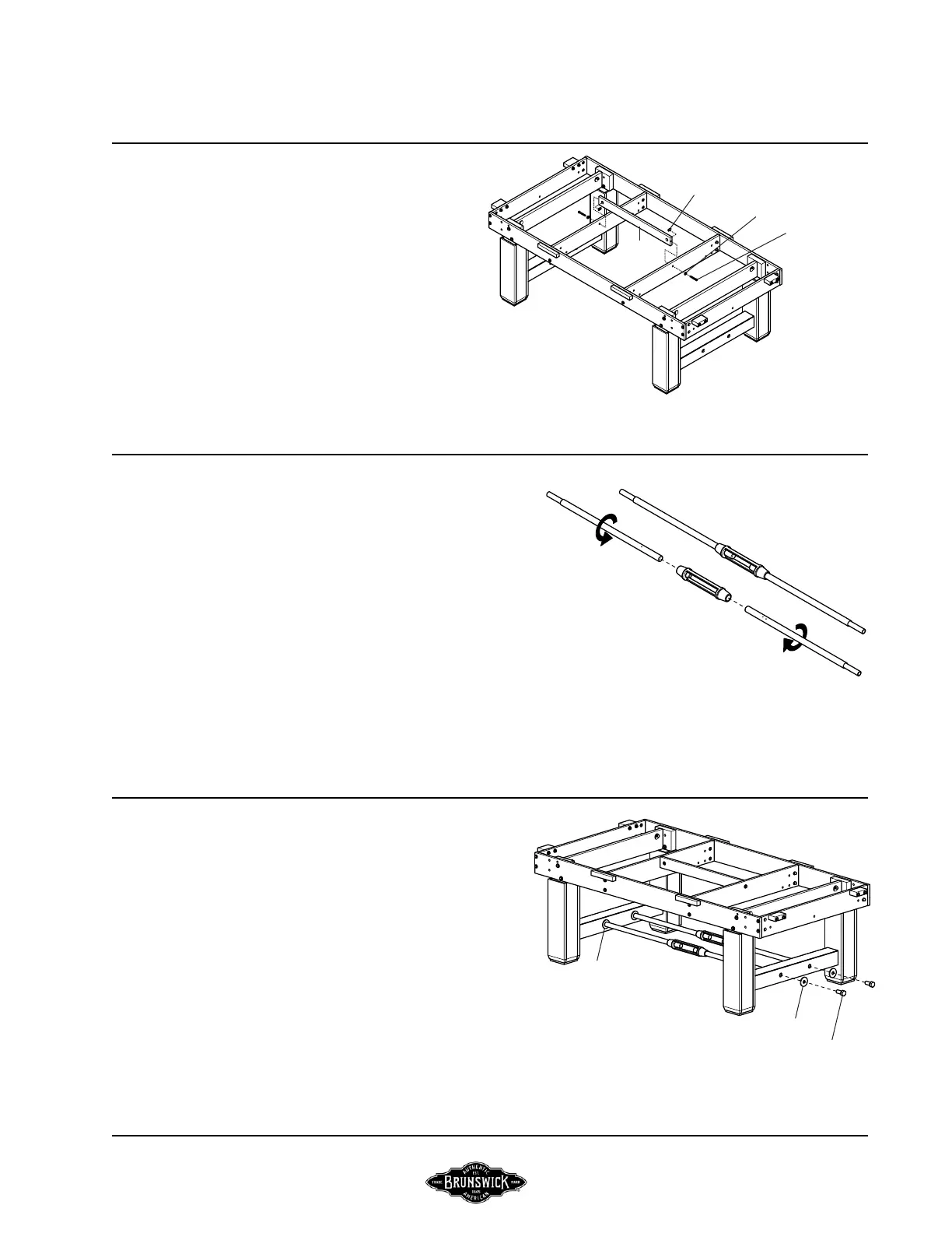
Step #9: Assemble two stretchers using one Right Hand
threaded rod, one Left Hand threaded rod and one turn-
buckle. Thread designation is dened by small, shallow
holes drilled into each part at the mating ends. Two holes
denes Right Hand threads and the one hole denes Left Hand
threads. Each rod will need to be threaded into the turn-
buckle 4-5 inches to start with.
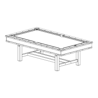
Step #10: For each stretcher bar assembly, unscrew each
bar simultaneously until each end is fully engaged. Fasten
each end with 3/4-10 x 2” socket head cap screw, 3/4 at
washer and adjust the span. The span at each foot should
be equal to the span at the top of each leg that has been
bolted to each side sill.
3/4-10 x 2”
HEX HEAD SCREW
3/4 WASHER
3/4 WASHER
PAGE 4 BRUNSWICK INSTALLATION MANUAL
E