34
SEE NOTES: 1,2,4,5,7,8,9 on the page
following these figures
A03215
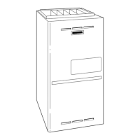
Fig. 46 -- Horizontal Left Application -- Vent Elbow Up
SEE NOTES: 1,2,4,5,7,8,9 on the page
following these figures
A03216
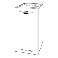
Fig. 47 -- Horizontal Left Application -- Vent Elbow Right
SEE NOTES: 1,2,4,5,7,8,9 on the page
following these figures
A03219
Fig. 48 -- Horizontal Right Application -- Vent Elbow Left
then Up
SEE NOTES: 1,2,4,5,7,8,9
A02068
Fig. 49 -- Horizontal Right Application--Vent Elbow Left
Caution!! For the following applications, use the minimum vertical heights as specified below.
For all other applications, follow exclusively the National Fuel Gas Code.
FURNACE ORIENTA-
TION
VENT ORIENTA TION FURNACE INPUT (BTUH/
HR)
MIN. VENT DIAME-
TER (IN.)*
MIN. VERTICAL VENT HEIGHT
(FT.)**
Downflow
Vent elbow left, then up
Fig. 37
154,000 132,000
110,000(036/---12 on ly)
5 12
Horizontal Left
Vent elbow right, then up
Fig. 40
154,000 132,000 5 7
Horizontal Left
Vent Elbow up
Fig. 41
154,000 132,000 5 7
Horizontal Left
Vent elbow right
Fig. 42
154,000 5 7
Downflow
Vent elbow up then left Fig.
35
110,000 (036/---12 only) 5 10
Downflow
Vent elbow up, then right
Fig. 38
110,000 (036/---12 only) 5 10
NOTE: All vent configurations must also meet National Fuel Gas Code
venting requirements NFGC.
*4 in. inside casing or vent guard
**Including 4 in. vent section(s)
315A
 Loading...