5
a person’s hand during grounding will be satisfactorily
discharged.
3. After touching the chassis, you may proceed to service the
control or connecting wires as long as you do nothing to
recharge your body with static electricity (for example;
DO NOT move or shuffle your feet, do not touch
ungrounded objects, etc.).
4. If you touch ungrounded objects (and recharge your body
with static electricity), firmly touch a clean, unpainted
metal surface of the furnace again before touching control
or wires.
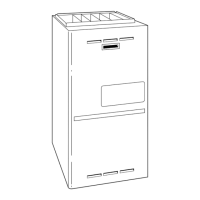
2-7/16"
1-1/8"
28-7/8"
25-1/4"
22-9/16"
JUNCTION BOX
LOCATION
7/8" DIA
ACCESSORY
1/2" DIA THERMOSTAT
WIRE ENTRY
3-15/16"
LEFT HAND GAS
ENTRY
33-5/16"
24-7/8"
5-1/2"
7/8" DIA. ACCESSORY
11/16"
21-5/8"
BOTTOM INLET
1-11/16"
13/16"
11/16"
4-13/16"
AIRFLOW
19"
OUTLET
13/16"
11/16"
8-9/16"
VENT OUTLET
5 PLACES (TYP)
3-3/4"
1-3/4" DIA.RIGHT HAND
GAS ENTRY
7/8" DIA. K.O. WIRE ENTRY
SIDE INLET
14-7/8"
7/8" DIA. ACCESSORY
1-1/4"
1"
22-1/16"
A
D
F
E
(FLUE COLLAR)
5-15/16"
24"
CASING
1-5/16"
1/2" DIA. K.O.THERMOSTAT
WIRE ENTRY
ALTERNATE
JUNCTION BOX
LOCATIONS (TYP)
26-1/8"
1-1/2"
7-3/4"
9-5/8"
11-1/2"
5-1/2"
NOTES:
1. Two additional 7/8-in. diameter holes are located in the top plate.
2. Minimum return-air openings at furnace, based on metal duct. If flex duct is used, see flex duct manufacturer’s recommendations for equivalent diameters.
a. For 800 CFM-16-in. round or 14 1/2 x 12-in. rectangle.
b. For 1200 CFM-20-in. round or 14 1/2 x 19 1/2-in. rectangle.
c. For 1600 CFM-22-in. round or 14 1/2 x 22-in. rectangle.
d. For airflow requirements above 1800 CFM, see Air Delivery table in Product Data literature for specific use of single side inlets. The use of both side inlets
a combination of 1 side and the bottom, or the bottom only will ensure adequate return air openings for airflow requirements above 1800 CFM.
A04037
NOTES: 1. Two additional 7/8---in. diameter holes are located in the top plate. 2. Minimum return---air openings at furnace, based on metal duct. If flex duct is
used, see flex duct manufacturer’s recommendations for equivalent diameters. a. For 800 CFM---16---in. round or 14 1/2 x 12---in. rectangle. b. For 1200
CFM---20 ---in. round or 14 1/2 x 19 1/2 ---in. rectangle. c. For 1600 CFM ---22---in. rou nd or 14 1/2 x 22 1/16---in. rectangle. d. For airflow requirements above 1800
CFM, see Air Delivery table in Product Data literature for specific use of single side inlets. The use of both side inlets, a combination of 1 side and the bottom, or
the bottom only will ensure adequate return air openings for airflow requirements above 1800 CFM.
Fig. 3 -- Dimensional Drawing
Table 1 – Dimensions (IN.)
FURNACE
SIZE
A
CABINET
WIDTH (IN.)
D
SUPPLY ---
AIR WIDTH
(IN.)
E
RETURN ---
AIR WIDTH
(IN.)
F
CENTER LINE TOP AND
BOTTOM FLUE COL-
LAR (IN.)
FLUE
COLLAR* (IN.)
SHIP WT.
(LB)
FIL TER ME-
DIA CABINET
SIZE (IN.)
070---12/03607
0
14---3/16 12---9/16 12---11/16 9---5/16 4 127 16
090---16/04809
0
17---1/2 15---7/8 16 11---9/16 4 151 16
110---20/06011
0
21 19---3/8 19---1/2 13---5/16 4 163 20
135---22/06613
5
24---1/2 22---7/8 23 15---1/16 4† 177 24
155---22/06615
5
24---1/2 22---7/8 23 15---1/16 4† 183 24
*5” or 6” vent connector may be required in some cases.
{5” or larger vent is required. Use a 4 ---5 or 4 ---6 inch vent adapter be-
tween furnace and vent connector.
5. Use this procedure for installed and uninstalled
(ungrounded) furnaces.
6. Before removing a new control from its container,
discharge your body’s electrostatic charge to ground to
protect the control from damage. If the control is to be
installed in a furnace, follow items 1 through 4 before
bringing the control or yourself in contact with the
furnace. Put all used and new controls into containers
before touching ungrounded objects.
7. An ESD service kit (available from commercial sources)
mayalsobeusedtopreventESDdamage.
LOCATION
GENERAL
This multipoise furnace is shipped in packaged configuration.
Some assembly and modifications are required when used in any
of the four applications shown in Fig. 4.
NOTE: For high--altitude installations, the high--altitude
conversion kit MUST be installed at or above 5500 ft. above sea
315A
 Loading...