or high-gas-heat speed. Simultaneously, the EAC termi-
nals EAC-1 and EAC-2 are energized with 115v and
remain energized as long as blower motor BLWM is
energized.
f. Switching from low- to high-gas heat—If furnace control
CPU switches from low-gas heat to high-gas heat, the
control CPU switches inducer motor IDM speed from
low to high. The high-heat pressure switch relay HPSR
closes. When inducer motor IDM provides sufficient
pressure to close the high-heat pressure switch HPS, the
high-heat gas valve solenoid GV is energized. The
blower motor BLWM switches speed for high-gas heat 5
sec after the control CPU switches from low-gas heat to
high-gas heat.
g. Switching from high- to low-gas heat—The control CPU
will not switch from high-gas heat to low-gas heat while
the thermostat R to W circuit is closed when a single-
stage thermostat is used.
h. Blower off delay—When thermostat is satisfied, the
R-W circuit is opened, de-energizing gas valve GV,
stopping gas flow to burners, and de-energizing humidi-
fier terminals HUM and C
OM. The inducer motor IDM
remains energized for a 5 sec post-purge period. The
blower motor BLWM and EAC terminals EAC-1 and
EAC-2 remain energized for 90, 135, 180, or 225 sec
(depending on selection at blower off delay switches
SW-3 and SW-4). The furnace control CPU is factory set
for a 135-sec blower off delay.
2. Non-Adaptive Heating Mode—Two-Stage Thermostat and
2-Stage Heating
(See Fig. 10 for thermostat connections).
NOTE: The low-heat-only switch SW-2 in ON position selects
low-heat-only operation mode in response to closing the thermo-
stat R-W1 circuit. When high-heat-only switch SW-1 is in OFF
position, closing the thermostat R to W1 and W2 circuits is
required for high-gas-heat operation. When high-heat-only switch
SW-1 is on, it always causes high-gas-heat operation when R-W1
circuit is closed, regardless of the setting of the low-heat-only
switch SW-2 and regardless of whether R-W2 circuit is closed or
open.
When the wall thermostat "calls for heat", R-W/W1 circuit
closes for low-gas heat or R to W1-and-W2 circuits close
for high-gas heat. The furnace control performs a self
check, verifies low-heat and high-heat pressure switch
contacts LPS and HPS are open, and starts inducer motor
IDM in low speed or high speed as appropriate.
The start-up and shutdown functions and delays described
in item 1 above apply to 2-stage heating mode as well,
except for switching from low- to high-gas heat and vice
versa.
a. Switching from low- to high-gas heat—If thermostat
R-W/W1 circuit for low-gas heat is closed and R-W2
circuit for high-gas- heat closes, the control CPU
switches the inducer motor IDM speed from low to high.
The high-heat pressure switch relay HPSR closes. When
inducer motor IDM provides sufficient pressure to close
high-heat pressure switch HPS, the high-heat gas valve
solenoid GV is energized. The blower motor BLWM
switches speed for high-gas heat 5 sec after R-W2 circuit
closes.
b. Switching from high- to low-gas heat—If thermostat
R-W2 circuit for high-gas heat opens and R to W/W1
circuit for low-gas heat remains closed, the control CPU
will switch inducer motor IDM speed from high to low.
The high-heat pressure switch relay HPSR will open to
de-energize high-heat gas valve solenoid GV. When
inducer motor IDM reduces pressure sufficiently, the
high-heat pressure switch HPS will open. The low-heat
gas valve solenoid GV remains energized as long as
low-heat pressure switch LPS remains closed. The
blower motor BLWM switches speed for low-gas heat 5
sec after R-W2 circuit opens.
3. Cooling Mode
a. Single-Speed Cooling Outdoor Unit
(See Fig. 9 for thermostat connections.)
(1.) The thermostat closes R to G-and-Y circuits. The
R-Y circuit starts the outdoor unit, and R to
G-and-Y circuits start the furnace blower motor
BLWM on high-cool speed.
(2.) The EAC terminals EAC-1 and EAC-2 are ener-
gized with 115v when blower motor BLWM is
operating.
(3.) When thermostat is satisfied, the R to G-and-Y
circuits are opened. The outdoor unit stops, and
furnace blower motor BLWM continues operating
on high-cool speed for an additional 90 sec.
b. Two-Speed Cooling Outdoor Unit
(See Fig. 10 for thermostat connections.)
(1.) The thermostat closes R to G-and-Y1 circuits for
low cooling or closes R to G-and-Y1-and-Y/Y2
circuits for high cooling. The R to Y1 circuits start
the outdoor unit on low-cooling speed, and the R-G
circuit starts furnace blower motor BLWM on
low-cooling speed (same speed as for low-gas heat).
The R to Y1-and-Y2 circuits start the outdoor unit
on high-cooling speed, and the R to G-and-Y2
circuits start furnace blower motor BLWM on
high-cooling speed.
NOTE: Y1 is found in the outdoor unit. The furnace control CPU
controls blower motor BLWM speed by sensing only G for
low-cooling speed and Y/Y2 for high-cooling speed.
(2.) The EAC terminals EAC-1 and EAC-2 are ener-
gized with 115v when blower motor BLWM is
operating on either cooling speed.
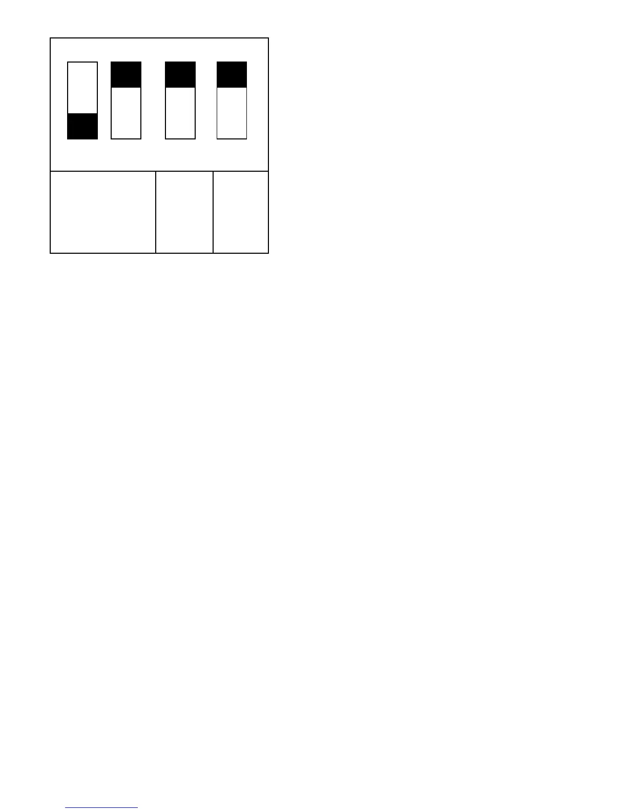
Fig. 12—Setup Switches on Control Center
(Factory Settings)
A96402
BLOWER-
OFF
DELAY
LOW
HEAT
(ADAPTIVE
ALGORITHM)
HIGH
HEAT
ONLY
43 2
OFF
ON
1
—12—