VII. GAS PIPING
Gas piping must be installed in accordance with national and local
codes. Refer to the NFGC NFPA 54-1999/ANSI Z223.1-1999.
Canadian installations must be installed in accordance with NSC-
NGPIC and all authorities having jurisdiction.
The gas supply line should be a separate line running directly from
the gas meter to the furnace, if possible. Refer to Table 4 for
recommended gas pipe size. Risers must be used to connect to
furnace and meter.
CAUTION: If a flexible connector is required or al-
lowed by the authority having jurisdiction, black iron
pipe shall be installed at the gas valve and extend a
minimum of 2 in. outside the furnace casing.
Piping should be pressure tested in accordance with local and
national plumbing and gas codes before furnace has been attached.
If test pressure exceeds 0.5 psig (14-in. wc), the gas supply pipe
must be disconnected from the furnace and capped before pressure
test. If test pressure is equal to or less than 0.5 psig (14-in. wc),
turn OFF electric shutoff switch before test. (See Fig. 7.) It is
recommended that the ground joint union be loosened before
pressure testing. After all connections have been made, purge lines
and check for leakage with regulated gas supply pressure.
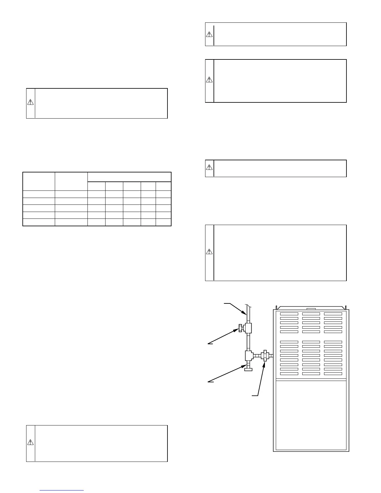
Install a sediment trap in riser leading to furnace. The trap can be
installed by connecting a tee to riser leading from the furnace.
Connect a capped nipple into lower end of the tee. The capped
nipple should extend below level of gas controls. (See Fig. 8.)
Apply joint compound (pipe dope) sparingly and only to male
threads of each joint. The compound must be resistant to action of
propane gas.
Install an accessible manual shutoff valve upstream of furnace gas
controls and within 72 in. of furnace. A 1/8-in. NPT plugged
tapping is provided on the gas valve for test gage connection.
Installation of an additional 1/8-in. NPT plugged tapping, acces-
sible for test gage connection, installed immediately upstream of
gas supply connection to furnace and downstream of manual
shutoff valve, is not required. Place ground joint union between
gas control manifold and manual shutoff valve.
WARNING: Use the proper length of pipes and ad-
equate piping support to avoid stress on the gas control
manifold. A failure to follow this warning can cause a gas
leak resulting in a fire, explosion, personal injury, or
death.
CAUTION: Use a backup wrench at the furnace gas
control when connecting the gas pipe to the furnace to
avoid damaging gas controls or manifold.
WARNING: Never purge a line into a combustion
chamber. Never use matches, candles, flame, or other
sources of ignition for the purpose of checking leakage.
Use a soap-and-water solution to check for leakage. A
failure to follow this warning can cause a fire, explosion,
personal injury, or death.
VIII. ELECTRICAL CONNECTIONS
A. 115-v Wiring
Refer to unit rating plate or Table 5 for equipment electrical
requirements. The control system requires an earth ground for
proper operation.
CAUTION: Do not connect aluminum wire between
disconnect switch and furnace. Use only copper wire.
Make all electrical connections in accordance with the National
Electrical Code (NEC) ANSI/NFPA 70-1999 and local codes or
ordinances that might apply. For Canadian installations, all elec-
trical connections must be made in accordance with CSA C22.1
Canadian Electrical Code, or authorities having jurisdiction.
WARNING: The cabinet MUST have an uninterrupted
or unbroken ground according to NEC ANSI/NFPA
70-1999 and Canadian Electrical Code, CSA C22.1 or
local codes to minimize personal injury if an electrical
fault should occur. This may consist of electrical wire or
conduit approved for electrical ground when installed in
accordance with existing electrical codes. Do not use gas
piping as an electrical ground.
TABLE 4—MAXIMUM CAPACITY OF PIPE*
NOMINAL
IRON PIPE
SIZE (IN.)
INTERNAL
DIAMETER
(IN.)
LENGTH OF PIPE (FT)
10 20 30 40 50
1/2 0.622 175 120 97 82 73
3/4 0.824 360 250 200 170 151
1 1.049 680 465 375 320 285
1-1/4 1.380 1400 950 770 660 580
1-1/2 1.610 2100 1460 1180 990 900
* Cubic ft of gas per hr for gas pressures of 0.5 psig (14-in. wc) or less, and a
supply line pressure drop of 0.5-in. wc (based on a 0.60 specific gravity gas).
Ref: Table 10-2, NFPA 54-1999.
Fig. 8—Typical Gas Pipe Arrangement
A89417
GAS
SUPPLY
MANUAL
SHUTOFF
VALVE
(REQUIRED)
SEDIMENT
TRAP
UNION
—8—