CAUTION: Connect gas pipe to furnace using a backup
wrench to avoid damaging gas controls.
WARNING: Gas valve knob MUST be facing forward
or tilted upward. Failure to follow this warning could
result in property damage or death.
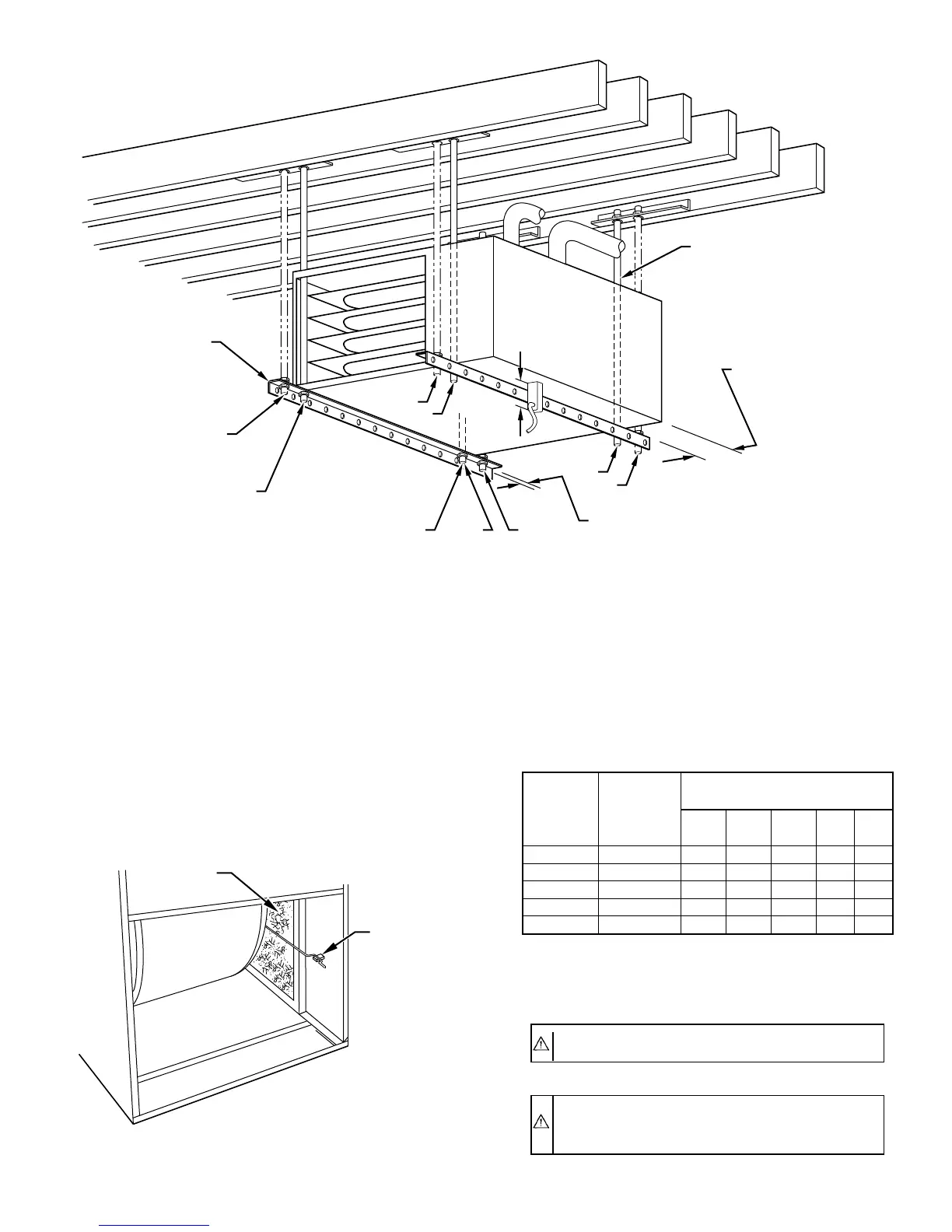
Fig. 17—Crawlspace Horizontal Application
A93304
NOTES:
ANGLE
IRON OR
EQUIVALENT
(B)
(A) ROD LOCATION
USING DIMPLE
LOCATORS
(SEE DIMENSIONAL
DWG FOR
LOCATIONS)
13
/16-IN. MAX
ALTERNATE SUPPORT
LOCATION FROM BACK
ALTERNATE SUPPORT
LOCATION 4-IN. MIN
8-IN. MAX
3
⁄8-IN. ROD
(A)
(B)
(A)
(B)
(B)
(A)
1. A 1 In. clearance minimum between top of
furnace and combustible material.
2. The entire length of furnace must be
supported when furnace is used in horizontal
position to ensure proper drainage.
(A) PREFERRED ROD LOCATION
(B) ALTERNATE ROD LOCATION
DRAIN
5
3
⁄
4
″
3
/8-IN. HEX NUT
& WASHER (4)
REQD PER ROD
Fig. 18—Filter Installed for Side Inlet
A93045
FILTER
RETAINER
WASHABLE
FILTER
TABLE 2—MAXIMUM CAPACITY OF PIPE*
NOMINAL
IRON
PIPE
SIZE
(IN.)
INTERNAL
DIAMETER
(IN.)
LENGTH OF PIPE (FT)
10 20 30 40 50
1/2 0.622 175 120 97 82 73
3/4 0.824 360 250 200 170 151
1 1.049 680 465 375 320 285
1-1/4 1.380 1400 950 770 660 580
1-1/2 1.610 2100 1460 1180 990 900
* Cubic ft of gas per hr for gas pressures of 0.5 psig (14-in. wc) or less, and a
pressure drop of 0.5-in. wc (based on a 0.60 specific gravity gas). Ref: Table
10-2 NFPA 54-1992.
—15—
 Loading...


