WARNING:
Blower access panel door switch opens 115-v power to
control center. No component operation can occur. Do
not bypass or close switch with panel removed. Failure to
follow this warning could result in personal injury or
death.
CAUTION: Furnace control must be grounded for
proper operation or control will lock out. Control is
grounded through green wire routed to gas valve and
burner box screw.
I. 115-V WIRING
Before proceeding with electrical connections, make certain that
voltage, frequency, and phase correspond to that specified on unit
rating plate. Also, check to be sure that service provided by utility
is sufficient to handle load imposed by this equipment. Refer to
rating plate or Table 3 for equipment electrical specifications.
Make all electrical connections in accordance with NEC
ANSI/NFPA 70-1993 and any local codes or ordinances that might
apply. For Canadian installations, all electrical connections must
be made in accordance with Canadian Electrical Code CSA C22.1
or subauthorities having jurisdiction.
Use a separate, fused branch electrical circuit containing a properly
sized fuse or circuit breaker for this furnace. See Table 3 for wire
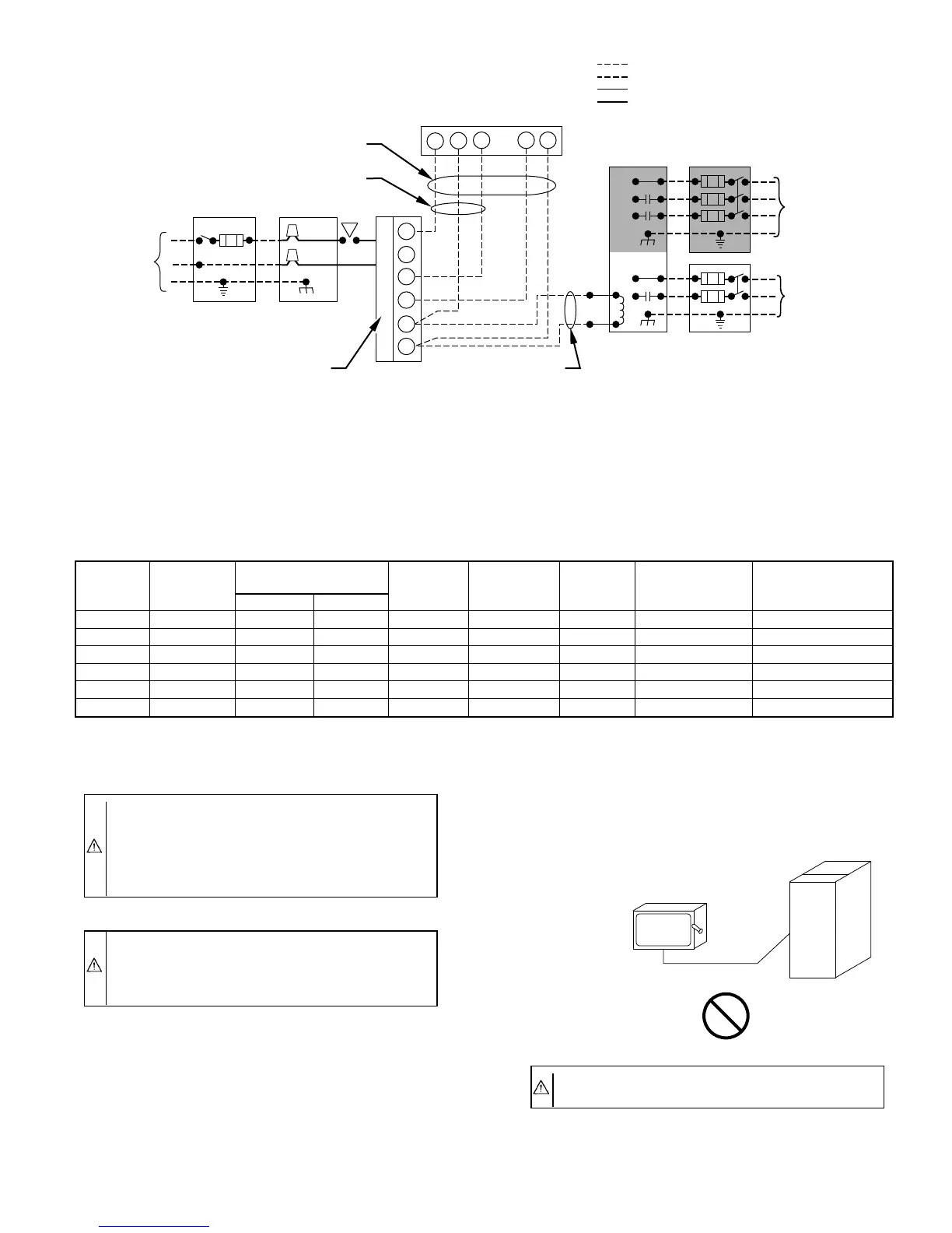
Fig. 22—Heating and Cooling Application Wiring Diagram
A95199
115-VOLT FIELD-
SUPPLIED
FUSED
DISCONNECT
115-VOLT
SINGLE
PHASE
AUXILIARY
J-BOX
FURNACE
CONTROL
CENTER
TWO WIRE
24-VOLT
TERMINAL
BLOCK
THREE-WIRE
HEATING
ONLY
FIVE
WIRE
NOTE 5
NOTE 1
NOTE
3
THERMOSTAT
TERMINALS
FIELD-SUPPLIED
FUSED DISCONNECT
CONDENSING
UNIT
R
W2
WCR GY
GND
GND
GND
GND
FIELD 24-VOLT WIRING
FIELD 115-, 208/230-, 460-VOLT WIRING
FACTORY 24-VOLT WIRING
FACTORY 115-, 208/230-, 460-VOLT WIRING
208/230- OR
460-VOLT
THREE
PHASE
208/230-
VOLT
SINGLE
PHASE
W/W1
Y/Y2
G
C
NOTES:
1.
2.
3.
4.
5.
Connect Y or Y/Y2 terminal as shown for proper cooling operation.
Proper polarity must be maintained for 115-volt wiring.
Use W2 with 2-stage thermostat when zoning.
If any of the original wire, as supplied, must be replaced, use
same type or equivalent wire.
Some thermostats require a "C" terminal connection as shown.
TABLE 3—ELECTRICAL DATA
UNIT
SIZE
VOLTS—
HERTZ—
PHASE
OPERATING
VOLTAGE RANGE
MAXIMUM
UNIT
AMPS
UNIT
AMPACITY†
MINIMUM
WIRE
SIZE
MAXIMUM WIRE
LENGTH (FT)‡
MAXIMUM FUSE OR
CKT BKR AMPS**
Maximum* Minimum*
042040 115—60—1 127 104 8.9 12.0 14 31 15
042060 115—60—1 127 104 8.9 12.0 14 31 15
042080 115—60—1 127 104 8.9 12.0 14 31 15
→060080 115—60—1 127 104 13.8 17.9 12 32 20
060100 115—60—1 127 104 13.8 18.1 12 32 20
→060120 115—60—1 127 104 11.2 14.7 14 25 15
* Permissible limits of voltage range at which unit will operate satisfactorily.
† Unit ampacity = 125 percent of largest operating component’s full load amps plus 100 percent of all other potential operating components’ (EAC, humidifier, etc.) full load
amps.
‡ Length shown is as measured 1 way along wire path between unit and service panel for maximum 2 percent voltage drop.
** Time-delay fuse is recommended.
CAUTION: Do not connect aluminum wire between
disconnect switch and furnace. Use only copper wire.
A93033
COPPER
WIRE ONLY
ELECTRIC
DISCONNECT
SWITCH
ALUMINUM
WIRE
—17—
→
 Loading...


