3. Insofar as is practical, close all building doors and windows
and all doors between space in which appliances remaining
connected to common vent system are located and other
spaces of building. Turn on clothes dryers and any appli-
ance not connected to common vent system. Turn on any
exhaust fans, such as range hoods and bathroom exhausts,
so they operate at maximum speed. Do not operate a
summer exhaust fan. Close fireplace dampers.
4. Follow lighting instructions and place appliance in opera-
tion. Adjust thermostat so appliance operates continuously.
5. Test for flue gas spillage at drafthood relief opening after 5
minutes of main burner operation. Use flame of a match or
candle, etc.
6. After it has been determined that each appliance remaining
connected to common vent system properly vents when
tested as above, return doors, windows, exhaust fans,
fireplace dampers, any other gas burning appliances to their
previous condition of use.
7. If improper venting is observed during any of above tests,
common vent system must be corrected. Vent system or
vent connectors may need to be resized. For any other
appliances when resizing vent systems or vent connectors,
system or connector must be sized to approach minimum
size as determined using appropriate table found in Part 11
of NFGC or Section 5 of NSCNGPIC.
II. COMBUSTION-AIR AND VENT PIPING
A. General
Combustion-air and vent pipe fittings must conform to American
National Standards Institute (ANSI) standards and American
Society for Testing and Materials (ASTM) standards D1785
(schedule-40 PVC), D2665 (PVC-DWV), D2241 (SDR-21 and
SDR-26 PVC), D2661 (ABS-DWV), F628 (schedule-40 ABS), or
F891 (PVC-DWV cellular core). Pipe cement and primer must
conform to ASTM standards D2564 (PVC) or D2235 (ABS). See
Table 5 for maximum pipe lengths and Fig. 31, 32, 33, 34, and 35
for exterior piping arrangements.
In Canada construct all combustion-air and vent pipes for this unit
of CSA or ULC certified schedule-40 PVC, PVC-DWV or
ABS-DWV pipe and pipe cement. SDR pipe is NOT approved in
Canada.
NOTE: Furnace combustion-air and vent pipe connections are
sized for 2-in. pipe. Any pipe size change should be made outside
furnace casing in vertical pipe. (See Fig. 27.) This allows proper
drainage of vent condensate.
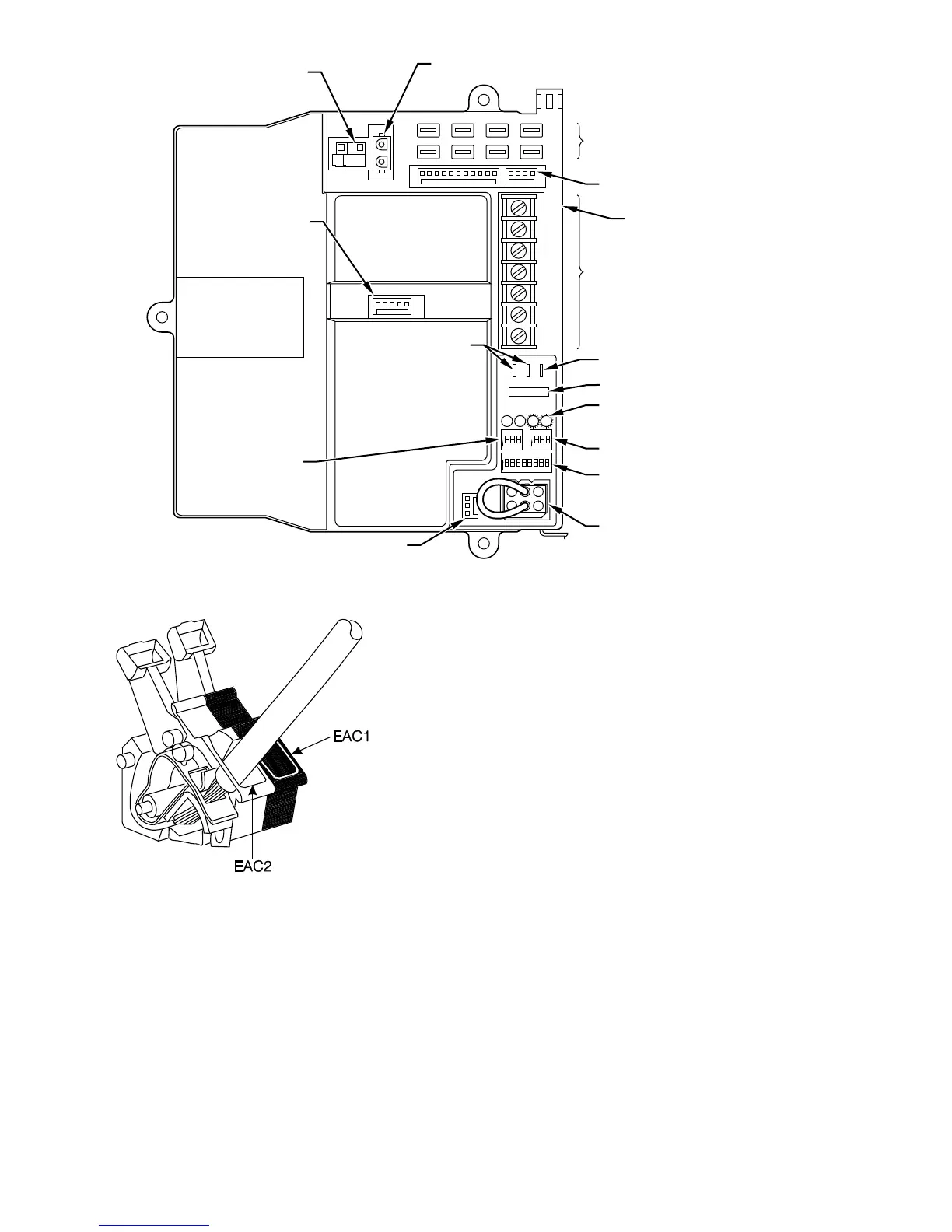
Fig. 25—Control Center
A93062
W2
COM
24V
W/W1 Y/Y2
RG
HUM
HOT SURFACE
IGNITOR CONNECTOR
EAC-ELECTRONIC AIR
CLEANER TERMINALS
(115-VAC 1 AMP MAX)
115-V
CONNECTORS
24-V THERMOSTAT
TERMINALS
PRESSURE SWITCH
CONNECTOR
HUM-HUMIDIFIER
TERMINAL
(24-VAC 0.5 AMP MAX)
TRANSFORMER
24-V CONNECTORS
3-AMP FUSE
STATUS AND DIAGNOSTIC
LED LIGHTS
AIR CONDITIONING
(A/C) SETUP SWITCH
SETUP SWITCHES
(SW) AND BLOWER
OFF DELAY SETUP
SWITCHES
MODEL PLUG
COMMUNICATION
CONNECTOR
CONTINUOUS
FAN (CF) SETUP
SWITCHES
MAIN BLOWER
CONTROL WIRE
CONNECTOR
DEHUMIDIFIER (DH)
CONNECTOR
Fig. 26—EAC Terminals on Control Center
A93053
—20—
 Loading...


