WARNING: Never purge a gas line into a combustion
chamber. Never use matches, candles, flame, or other
sources of ignition for purpose of checking leakage. Use
a soap-and-water solution to check for leakage. A failure
to follow this warning could result in fire, explosion,
personal injury, or death.
WARNING: Use proper length of pipe to avoid stress on
gas control manifold. Failure to follow this warning could
result in a gas leak resulting in fire, explosion, personal
injury, or death.
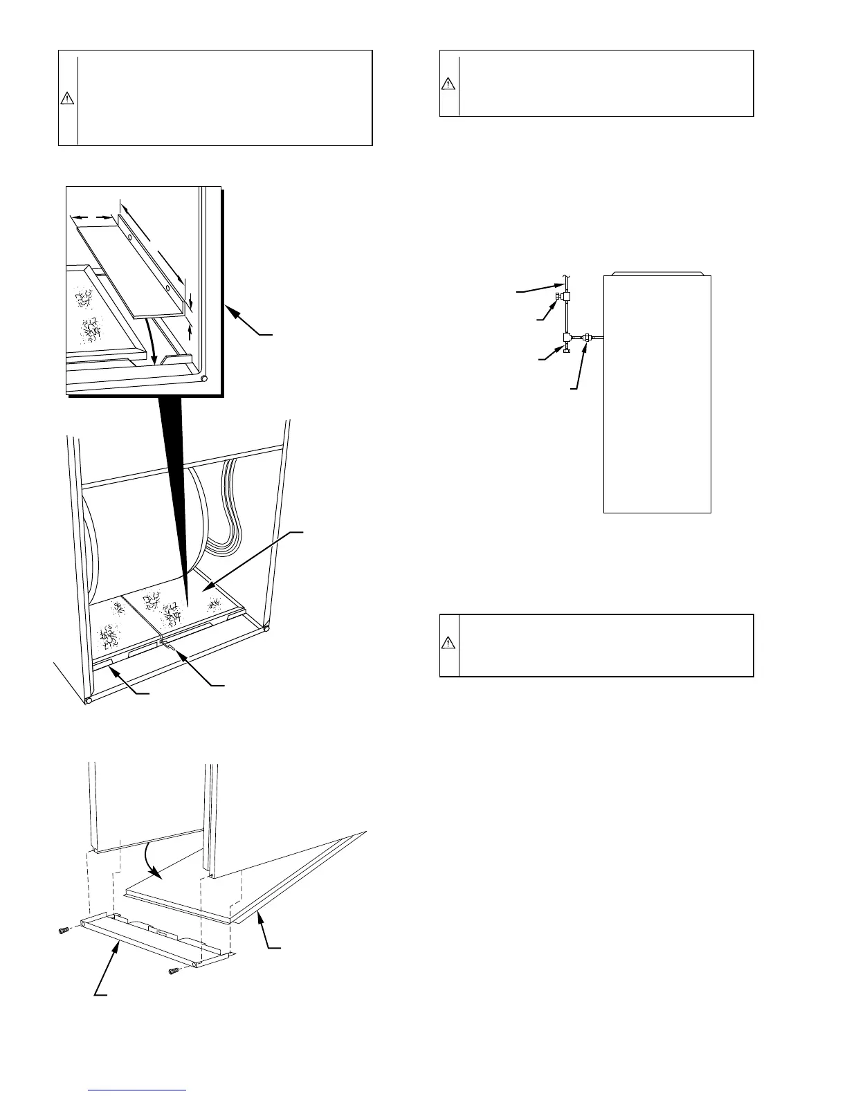
Install a sediment trap in riser leading to furnace. Trap can be
installed by connecting a tee to riser leading to furnace so
straight-through section of tee is vertical. Then connect a capped
nipple into lower end of tee. Capped nipple should extend below
level of gas controls. Place a ground joint union between gas
control manifold and manual gas shutoff valve. (See Fig. 21.)
CAUTION: If a flexible connector is required or al-
lowed by authority having jurisdiction, black iron pipe
shall be installed at gas valve and extend a minimum of
2 in. outside furnace casing.
An accessible manual shutoff valve MUST be installed upstream
of furnace gas controls and within 6 ft of furnace. A 1/8-in. NPT
plugged tapping, accessible for test gage connection, MUST be
installed immediately upstream of gas supply connection to
furnace and downstream of manual shutoff valve.
NOTE: The gas valve inlet press tap connection is suitable to use
as test gage connection providing test pressure DOES NOT exceed
maximum 0.5 psig (14-in. wc) stated on gas valve. (See Fig. 46.)
Piping should be pressure tested in accordance with local and
national plumbing and gas codes before furnace has been attached.
In Canada, refer to current edition of NSCNGPIC. If pressure
exceeds 0.5 psig (14-in. wc), gas supply pipe must be disconnected
from furnace and capped before pressure test. If test pressure is
equal to or less than 0.5 psig (14-in. wc), close manual shutoff
valve located on gas valve before test. It is recommended that
ground joint union be loosened before pressure testing. After all
connections have been made, purge lines and check for leakage.
ELECTRICAL CONNECTIONS
See Fig. 22 for field wiring diagram showing typical field 115-v
and 24-v wiring. Check all factory and field electrical connections
for tightness.
Fig. 19—Bottom Filter Arrangement
A93321
WASHABLE
FILTER
FILTER
SUPPORT
FILTER
RETAINER
FIELD-SUPPLIED
FILTER FILLER
STRIP FOR
17
1
⁄2-IN. WIDE
CASINGS ONLY.
INSTALL UNDER
FILTER.
1″
24
1
/
2
″
3″
Fig. 20—Removing Bottom Closure Panel
A93047
BOTTOM
CLOSURE
PANEL
FRONT FILLER
PANEL
Fig. 21—Typical Gas Pipe Arrangement
A93324
UNION
SEDIMENT
TRAP
MANUAL
SHUTOFF
VALVE
GAS
SUPPLY
—16—
 Loading...


