WARNING: All combustion-air and vent pipes must be
airtight and watertight. Pipes must also terminate exactly
as shown in Fig. 31, 32, 33, 34, or 35. Failure to follow
this warning could result in property damage, personal
injury, or death.
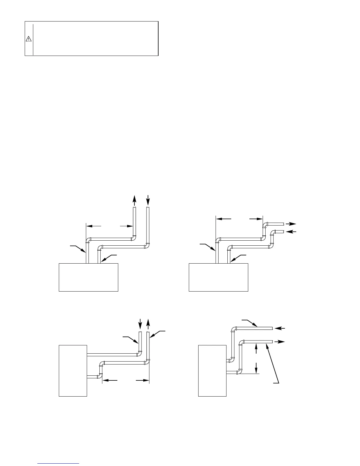
NOTE: The minimum combustion-air and vent pipe length (each)
for these furnaces is 5 ft. Short pipe lengths (5-8 ft) may discharge
water droplets. These droplets may be undesirable, and a 12-in.
minimum horizontal pipe section is recommended, as shown in
Fig. 29, to reduce excessive droplets from exiting vent pipe outlet.
B. Combustion-Air and Vent Pipe Diameter
Determine combustion-air and vent pipe diameter.
1. Using Table 5, determine preliminary combustion-air pipe
diameter.
2. Using Table 5, determine preliminary vent pipe diameter.
3. Use largest diameter pipe determined in 1. and 2. above for
both pipes.
NOTE: Do not count elbows or pipe sections in terminations or
within furnace. See shaded areas in Fig. 31, 32, 33, 34, and 35.
EXAMPLE:
An 042080 size furnace located in Indianapolis, elevation 650
ft above sea level, could be installed in an application requiring
3 elbows and 17 ft of vent pipe, along with 5 elbows and 16 ft
of combustion-air pipe. Table 5 indicates this application would
allow a 1-1/2-in. diameter vent pipe, but require a 2-in.
diameter combustion air pipe (1-1/2-in. pipe is good for 20 ft
with 3 elbows, but only 10 ft with 5 elbows). Therefore, 2-in.
diameter pipe must be used for both vent and combustion-air
pipes since larger required diameter must always be used for
both pipes. If same installation were in Albuquerque, elevation
5250 ft above sea level, installation would require 2-in. vent
pipe and combustion-air pipe. At 5001- to 6000-ft elevation,
1-1/2-in. pipe is not allowed with 5 elbows, and 2-in. pipe is
good for 68 ft with 5 elbows.
C. Combustion-Air and Vent Pipe Attachment
NOTE: All pipe joints must be watertight except attachment of
combustion-air pipe to inlet housing connection since it may be
necessary to remove pipe for servicing.
1. Attach combustion-air pipe as follows:
a. Determine location of combustion-air intake pipe con-
nection to combustion-air intake housing as shown in
Fig. 28 for application.
b. Reposition combustion-air intake housing plug fitting in
appropriate unused intake housing connection.
c. Insert perforated disk assembly (factory supplied) in
intake housing where combustion-air intake pipe will be
connected.
Fig. 29—Short Vent (5 to 8 Ft) System
A93591
HORIZONTAL TO ROOF HORIZONTAL TO SIDEWALL
VERTICAL TO SIDEWALLVERTICAL TO ROOF
VENT PIPE
COMBUSTION-AIR PIPE COMBUSTION-AIR PIPE
VENT PIPE
COMBUSTION-AIR PIPE
VENT PIPE
COMBUSTION-AIR PIPE
VENT PIPE
12″ MIN
12″ MIN
12″ MIN
12″ MIN
NOTE: A 12-in. minimum horizontal pipe section is recommended with
short (5 to 8 ft) vent systems. This recommendation is to reduce
excessive condensate droplets from exiting the vent pipe.
—22—
 Loading...


