11
C
B
D
A
C12384
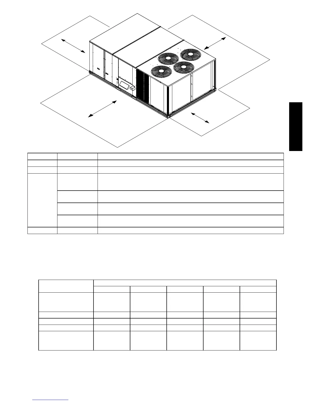
LOCATION DIMENSION CONDITION
A 36--- in (914 mm) • Recommended clearance for air flow and service
B 42---in (1067 mm) • Recommended clearance for air flow and service
C
18--- in (457 mm)
• No Convenience Outlet
•NoEconomizer
• No field installed disconnect on economizer hood side (Factory--- installed disconnect installed).
36--- in (914 mm)
• Convenience Outlet installed.
• Vertical surface behind servicer is electrically non--- conductive (e.g.: wood, fiberglass).
42--- in (1067 mm)
• Convenience Outlet installed.
• Vertical surface behind servicer is electrically conductive (e.g.: metal, masonry).
96--- in (2438 mm)
• Economizer and/or Power Exhaust installed.
• Check for sources of flue products with 10 feet (3 meters) of economizer fresh air intake.
D 42--- in (1067 mm) • Recommended clearance for service.
NOTE: Unit not designed to have overhead obstruction. Contact Application Engineering for guidance on any application planning
overhead obstruction or for vertical clearances.
Fig. 5 -- Service Clearance Dimensional Drawing
Table 1 – Operating Weights
580J*
UNIT LB (KG)
17 20 24 28 30
Base Unit
Novation™ Coil 1824 (829) 1839 (836) 1989 (904) 2118 (963) N/A
RTPF Coil 1907 (867) 1922 (874) 2072 (942) 2197 (999) 2640 (1200)
Economizer 246 (112) 246 (112) 246 (112) 246 (112) 246 (112)
Powered Outlet 35 (16) 35 (16) 35 (16) 35 (16) 35 (16)
Perfect Humidity™ System 110 (50) 110 (50) 120 (54) 120 (54) N/A
Curb
14--- in/356 mm 240 (109) 240 (109) 255 (116) 255 (116) 255 (116)
24--- in/610 mm 340 (154) 340 (154) 355 (161) 355 (161) 355 (161)
580J-- 17-- 30--V

 Loading...