31
Table 5 – RTU Open Controller Inputs and Outputs
POINT NAME04
BACnet OBJECT
NAME
TYPE OF I/O
CONNECTION PIN
NUMBER(S)
DEDICATED INPUTS
Space Temp / Zone Temp zone_temp AI (10K Thermistor) J 2 0 --- 1 & 2
Supply Air Temperature sa_temp AI (10K Thermistor) J 2 --- 1 & 2
Outdoor Air Temperature oa_temp AI (10K Thermistor) J 2 --- 3 & 4
Space Temperature Offset Pot stpt_adj_offset AI (100K Potentiometer) J 2 0 --- 3 & 4
Safety Chain Feedback safety_status DI (24 VAC) J 1 --- 9
Compressor Safety Status comp_status DI (24 VAC) J 1 --- 2
Fire Shutdown Status firedown_status DI (24 VAC) J 1 --- 1 0
Enthalpy Status enthalpy_status DI (24 VAC) J 2 --- 6 & 7
Humidistat Input Status humstat_status DI (24 VAC) J 5 --- 7 & 8
Zone Temperature n/a n/a J13--- 1, 2, 3, 4
CONFIGURABLE INPUTS
Indoor Air CO2 iaq A I ( 4 --- 2 0 m a )
J 4 --- 2 & 3 o r J 4 --- 5 & 6Outdoor Air CO2 oaq A I ( 4 --- 2 0 m a )
Space Relative Humidity space_rh A I ( 4 --- 2 0 m a )
Supply Fan Status* sfan_status DI (24 VAC)
J 5 --- 1 o r J 5 --- 3 o r J 5 --- 5
Filter Status* filter_status DI (24 VAC)
Door Contact Input* door_contact_status DI (24 VAC)
Occupancy Contact* occ_contact_status DI (24 VAC)
OUTPUTS
Economizer Output econ_output A O ( 4 --- 2 0 m a ) J 2 --- 5
SupplyFanRelayState sfan DO Relay (24VAC , 1A) J 1 --- 4
Compressor 1 Relay State comp_1 DO Relay (24VAC , 1A) J 1 --- 8
Compressor 2 Relay State comp_2 DO Relay (24VAC , 1A) J 1 --- 7
Heat Stage 1 Relay State heat_1 DO Relay (24VAC , 1A) J 1 --- 6
Heat Stage 2 Relay State heat_2 DO Relay (24VAC , 1A) J 1 --- 5
Power Exhaust Relay State pexh DO Relay (24VAC , 1A) J 1 1 --- 1 & 3
Perfect Humidity Relay State dehum DO Relay (24VAC, 1A) J 1 1 --- 7 , 8
LEGEND
AI --- An a l o g I n pu t
AO --- A n a l o g O u t p u t
DI --- D isc r e t e I n p u t
DO --- Discrete Output
* These inputs (if installed) take the place of the default input on the specific channel according to schematic.
Pa r a l l e l pi n s J 5 --- 1 = J 2 --- 6 , J5 --- 3 = J 1 --- 1 0 , J 5 --- 5 = J 1 --- 2 a r e u s e d f o r f i e l d --- i n st a l l a t i o n .
The RTU Open controller requires the use of a Bryant
space sensor. A standard thermostat cannot be used with
the RTU Open system.
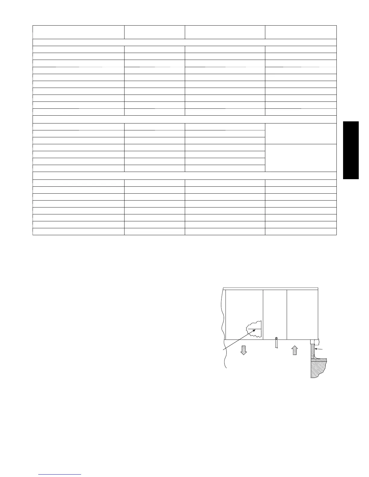
Supply Air Temperature (SAT) Sensor —
On FIOP--equipped 580J units, the unit is supplied with a
supply--air temperature (SAT) sensor (33ZCSENSAT). This
sensor is a tubular probe type, approx 6--inches (152 mm) in
length. It is a nominal 10--k ohm thermistor.
The SAT is factory--wired. The SAT probe is wire--tied to the
supply--air opening in its shipping position. Remove the
sensor for installation. Re--position the sensor in the flange
of the supply--air opening or in the supply air duct (as
required by local codes). Drill or punch a
1
/
2
--in. hole in the
flange or duct. Use two field--supplied, self--drilling screws
to secure the sensor probe in a horizontal orientation. See
Fig. 40.
Outdoor Air Temperature (OAT) Sensor —
The OAT is factory--mounted in the EconoMi$er2 (FIOP or
accessory). It is a nominal 10k ohm thermistor attached to
an eyelet mounting ring.
SUPPLY AIR
TEMPERATURE
SENSOR
SUPPLY AIR
RETURN AIR
ROOF
CURB
C13783
Fig. 40 -- Mounting Location for Supply Air
Temperature (SAT) Sensor on 580J Units
580J-- 17-- 30--V

 Loading...