19
15
14
13
12
11
10
9
8
7
6
5
4
3
2
1
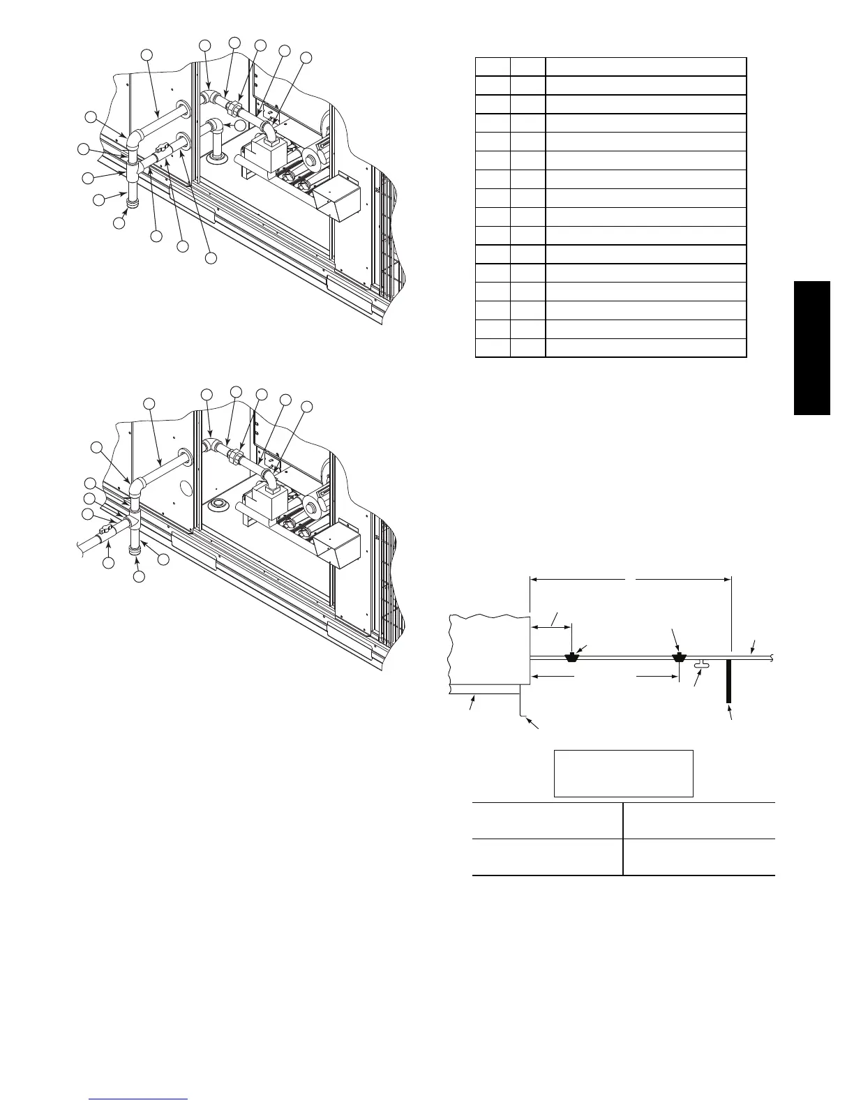
C10999
Fig. 17 -- Gas Supply Line Piping with Thru--Base
13
12
11
10
9
8
7
6
5
4
3
2
1
C101006
Fig. 18 -- Gas Supply Line Piping
Table 4 – Typical
3
/
4
--in NPT Field Supplied Piping Parts
Item Qty Description
1 1 90 Deg Street Elbow
2 1 5 Inch Long Nipple
3 1 Ground---Joint Union
4 1 3 Inch Long Nipple
5 1 90 Deg Elbow
6 1 12 Inch Long Nipple
7 1 90 Deg Elbow
8 1 3 Inch Long Nipple
9 1 TEE
10 1 4 Inch Long Nipple (Sediment Trap)
11 1 Cap
12 1 3
1
/
2
Inch Long Nipple
13 1 NIBCO
R
Ball V alve (PN: GB30)
14 1 8 Inch Long Nipple
15 1 90 Deg Elbow
Install a gas supply line that runs to the unit heating
section. Refer to the NFPA 54/NFGC or equivalent code
for gas pipe sizing data. Do not use a pipe smaller than the
size specified. Size the gas supply line to allow for a
maximum pressure drop of 0.5--in wg (124 Pa) between
gas regulator source and unit gas valve connection when
unit is operating at high--fire flow rate.
The gas supply line can approach the unit in two ways:
horizontally from outside the unit (across the roof), or
through unit basepan. Observe clearance to gas line
components per Fig. 19.
LEGEND
*
Field supplied.
NOTE: Follow all local codes.
NFGC – National Fuel Gas Code
STEEL PIPE
NOMINAL DIAMETER
(in.)
SPACINGOFSUPPORTS
X DIMENSION
(ft)
1
/
2
3
/
4
or 1
1
1
/
4
or larger
6
8
10
X
BASE UNIT
BASE RAIL
ROOF
CURB
9” MINIMUM CLEARANCE
FOR PANEL REMOVAL
MANUAL GAS
SHUTOFF VALVE
*
GAS
REGULATOR
*
48” MINIMUM
DRIP LEG
PER NFGC
*
FIELD-
FABRICATED
SUPPORT
*
FROM
GAS
METE
C11121
Fig. 19 -- Gas Piping Guide
580J-- 17-- 30--V

 Loading...