—32—
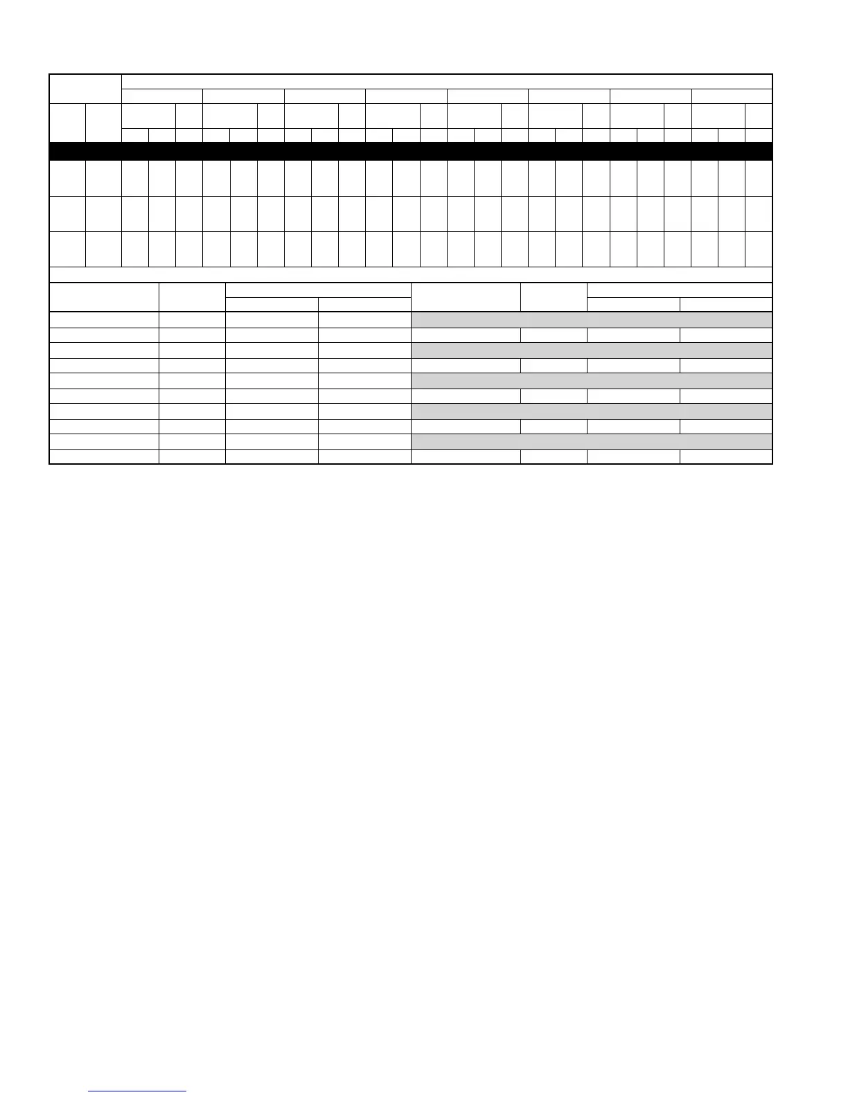
NOTE: When the required data fall between the published data, interpolation may be performed. Extrapolation is not an acceptable practice.
* The Btuh heating capacity values shown are net integrated values from which the defrost effect has been subtracted. The Btuh heating from supplement
heaters should be added to those values to obtain total system capacity.
† The kW values include the compressor, outdoor fan motor, and indoor blower motor. The kW from supplement heaters should be added to these values to
obtain total system kilowatts.
EDB—Entering Dry Bulb
INDOOR
AIR
OUTDOOR COIL ENTERING AIR TEMPERATURES °F
–3 7 17 2737475767
EDB CFM
Capacity
MBtuh†
Total
Pwr
Capacity
MBtuh†
Total
Pwr
Capacity
MBtuh†
Total
Pwr
Capacity
MBtuh†
Total
Pwr
Capacity
MBtuh†
Total
Pwr
Capacity
MBtuh†
Total
Pwr
Capacity
MBtuh†
Total
Pwr
Capacity
MBtuh†
Total
Pwr
Total Int* kW† Total Int* kW† Total Int* kW† Total Int* kW† Total Int* kW† Total Int* kW† Total Int* kW† Total Int* kW†
650A060-D, E Outdoor Section With FV4(A,B)NB006 Indoor Section
65
1750 25.4 23.3 3.70 31.5 28.9 3.89 37.6 34.2 4.05 44.1 39.2 4.23 51.9 47.2 4.44 60.8 60.8 4.70 71.5 71.5 5.04 83.8 83.8 5.42
2000 25.8 23.7 3.73 31.9 29.3 3.89 37.9 34.6 4.04 44.6 39.6 4.19 52.4 47.7 4.39 61.5 61.5 4.63 72.5 72.5 4.95 84.0 84.0 5.25
2250 26.2 24.1 3.77 32.3 29.7 3.91 38.2 34.9 4.04 45.0 40.0 4.19 52.9 48.2 4.37 62.2 62.2 4.59 73.3 73.3 4.90 84.5 84.5 5.17
70
1750 24.5 22.5 3.87 30.9 28.4 4.08 37.2 33.9 4.28 43.7 38.8 4.46 51.2 46.6 4.68 60.0 60.0 4.95 70.5 70.5 5.30 82.6 82.6 5.71
2000 25.0 23.0 3.90 31.3 28.8 4.09 37.6 34.3 4.26 44.1 39.2 4.42 51.8 47.1 4.62 60.7 60.7 4.87 71.4 71.4 5.20 83.7 83.7 5.57
2250 25.4 23.3 3.94 31.7 29.1 4.11 37.9 34.6 4.26 44.5 39.5 4.41 52.3 47.6 4.60 61.3 61.3 4.83 72.2 72.2 5.14 83.6 83.6 5.44
75
1750 23.4 21.6 4.01 30.1 27.7 4.27 36.8 33.6 4.51 43.2 38.4 4.70 50.6 46.1 4.93 59.2 59.2 5.21 69.4 69.4 5.58 81.5 81.5 6.05
2000 23.9 22.0 4.05 30.6 28.1 4.28 37.2 33.9 4.49 43.7 38.8 4.66 51.2 46.6 4.87 59.9 59.9 5.12 70.3 70.3 5.46 82.4 82.4 5.84
2250 24.4 22.4 4.09 31.0 28.5 4.31 37.6 34.3 4.49 44.1 39.1 4.65 51.7 47.0 4.84 60.5 60.5 5.08 71.1 71.1 5.40 83.0 83.0 5.73
Multipliers for Determining the Performance With Other Indoor Sections
Indoor
Section Size
Heating
Indoor
Section Size
Heating
Capacity Power Capacity Power
CC5A/CD5AW 060 0.98 1.06
COILS + 315(A,J)AV066110 VARIABLE-SPEED FURNACE
CD5PX 060 1.00 1.03 CD5PX 060 0.98 0.99
CK5A/CK5BX 060 0.98 1.02
COILS + 315(A,J)AV066155 VARIABLE-SPEED FURNACE
CK5PX 060 0.98 1.02 CC5A/CD5AW 060 0.98 1.06
FB4BNB 070 1.00 1.03
COILS + 355MAV060080 VARIABLE-SPEED FURNACE
FC4CNB 070 1.00 1.03 CD5PX 060 1.00 1.06
FE4ANB 006 1.00 1.00
COILS + 355MAV060100 VARIABLE-SPEED FURNACE
FK4DNB 006 0.99 0.99 CD5PX 060 1.00 1.05
FV4BNB 006 1.00 1.00
COILS + 355MAV060120 VARIABLE-SPEED FURNACE
FX4BNB 060 1.00 1.03 CD5PX 060 1.02 1.06
HEAT PUMP HEATING PERFORMANCE Continued
System Design
1. Intended for outdoor installation with free air inlet and outlet. Outdoor fan external static pressure available is less than 0.01-in. wc.
2. Minimum outdoor operating air temperature for cooling mode without low-ambient operation accessory is 55°F (12.8°C).
3. Maximum outdoor operating air temperature for cooling mode is 125°F (51.7°C).
4. Minimum outdoor operating air temperature for heating mode is –30°F (–34.4°C).
5. Maximum outdoor operating air temperature for heating mode is 66°F (18.9°C).
6. For reliable operation, unit should be level in all horizontal planes.
7. Maximum elevation of indoor coil above or below base of outdoor unit is: indoor coil above = 50 ft, indoor coil below = 150 ft. (See items 8 and
9 following).
8. For interconnecting refrigerant tube lengths greater than 50 ft horizontal and/or elevation differences between indoor and outdoor units greater than
20 ft, consult Residential Split-System Application Guideline and Service Manual for Air Conditioners and Heat Pumps using Puron Refrigerant.
9. If ANY refrigerant tubing is buried, provide a minimum 6-in. vertical rise to the valve connections at the unit. Refrigerant tubing lengths up to 36-in.
may be buried without further considerations. Buried refrigerant tubing lengths greater than 36 in. are not recommended.
10. Use only copper wire for electric connection at unit. Aluminum and clad aluminum are not acceptable for the type of connector provided.
11. Mismatches of indoor coil capacity more than 1 size larger than outdoor unit capacity (unless so specified) may result in inadequate indoor comfort.
12. Do not apply capillary tube indoor coils to these units.
13. Factory-supplied filter drier must be installed.