27
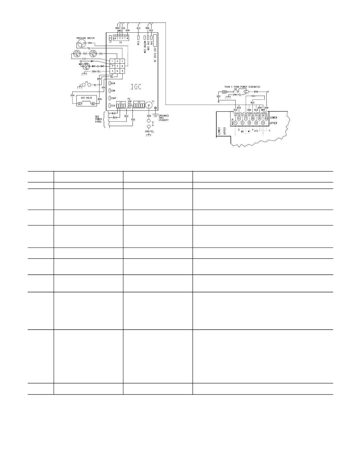
Fig. 44 — Typical IGC Control Wiring Diagram
LEGEND NOTES:
1. There is a 3-second pause between alarm code displays.
2. If more than one alarm code exists, all applicable alarm codes will
be displayed in numerical sequence.
3. Alarm codes on the IGC will be lost if power to the unit is interrupted.
UNIT CONTROL
BOARD
Table 5 — IGC Board LED Alarm Codes
FLASH
CODE
SYMPTOM CAUSE REMEDY
ON Normal Operation — —
OFF No Power or Hardware Failure Loss of power to control module
(IGC)
Check 5-amp fuse on the ICG, power to unit, 24V circuit breaker,
and transformer. Units without a 24V circuit breaker have an
internal overload in the 24V transformer. If the overload trips, allow
10 minutes for automatic reset.
1 Flash Check Fuse, Low Voltage Circuit Fuse is blown or missing, or
short circuit in secondary
(24 VAC) wiring.
Replace fuse if needed. Verify no short circuit in low voltage
(24 VAC) wiring.
2 Flashes Limit Switch Fault High temperature limit switch is
open.
Check the operation of the indoor (evaporator) fan motor.
Ensure that the supply-air temperature rise is in accordance with
the range on the unit nameplate.
Clean or replace filters.
3 Flashes Flame is Sense Fault The IGC sensed flame that
should not be present.
Reset unit. If problem persists, replace the IGC board.
4 Flashes Four Consecutive Limit Switch
Faults
Inadequate airflow to unit. Check the operation of the indoor (evaporator) fan motor and that
supply-air temperature rise agrees with range on the unit nameplate
information.
5 Flashes Ignition Lockout Fault Unit unsuccessfully attempted
ignition for 4 times.
Check igniter and flame sensor electrode spacing, gaps, etc.
Ensure that flame sense and ignition wires are properly terminated.
Verify that unit is obtaining proper amount of gas.
6 Flashes Pressure Switch Fault Open pressure switch. Verify wiring connections to pressure switch and inducer motor.
Verify pressure switch hose is tightly connected to both inducer
housing and pressure switch.
Verify inducer wheel is properly attached to inducer motor shaft.
Verify inducer motor shaft is turning. In 460V units check the
transformer designed for the inducer motor is operational. Also
check the fuses for the inducer motor transformer (460V units only).
7 Flashes Burner Thermal Switch Fault Burner thermal switch is open The burner thermal switch will automatically reset, but IGC will
continue to lockout unit.
Check any possible blockage in the access panel louver, intake
tube connected to the burner box, and the flue gas exhaust.
Check gas valve operation.
Ensure that induced-draft blower wheel is properly secured to motor
shaft.
Inspect the burner mesh inside the burner box by opening the side
window on the burner box.
Reset the unit disconnect.
8 Flashes Internal Control Fault Microprocessor has sensed an
error in the software or hardware.
If error code is not cleared by resetting unit power, replace the IGC
board.
IGC — Integrated Gas Unit Control
LED — Light-Emitting Diode

 Loading...


