43
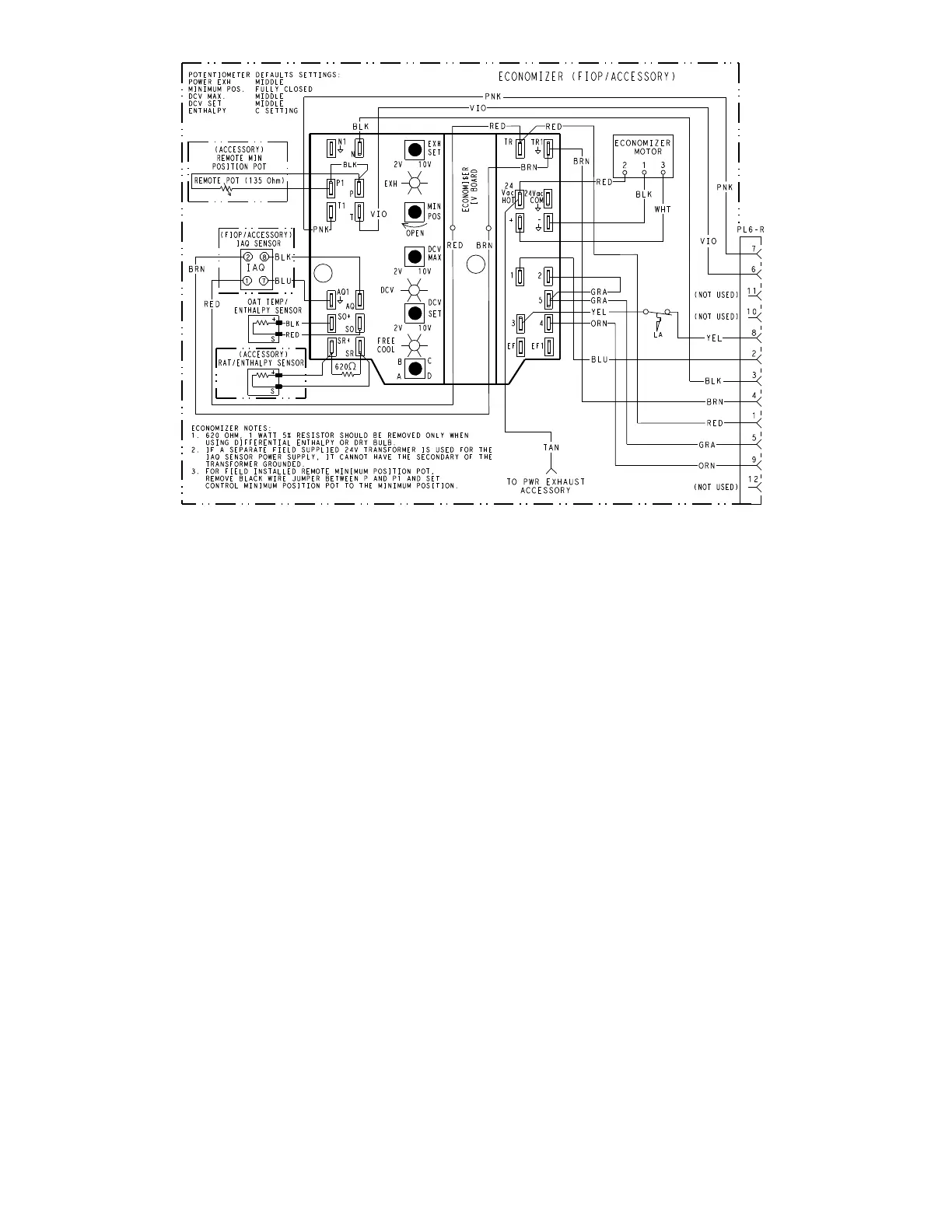
Fig. 54 — EconoMi$er IV Wiring
Step 14 — Adjust Factory-Installed Options
SMOKE DETECTORS
Smoke detector(s) will be connected at the Unit Control Board
(UCB), at terminals marked “Smoke Shutdown.” Detach the
jumper covering the Smoke Shutdown terminals on the UCB
and then attach the wiring harness from the smoke detector.
ECONOMI$ER IV OCCUPANCY SWITCH
See Fig. 54 for general EconoMi$er IV wiring. External occu-
pancy control is managed through a connection on the Unit
Control Board.
If external occupancy control is desired, connect a time clock
or remotely controlled switch (closed for Occupied, open for
Unoccupied sequence) at terminals marked OCCUPANCY.
Detach the jumper covering the “Occupancy” terminals on the
UCB and then attach the required connections.
Step 15 — Install Accessories
Available accessories include:
• Roof curb
• Thru-base connection kit (must be installed before unit is
set on curb)
• Flue discharge deflector
• Manual outside air damper
• Two-position motorized outside air damper
• EconoMi$er
®
IV (with control)
• EconoMi$er2 (without control/for external signal)
• Power Exhaust
• Differential dry-bulb sensor (EconoMi$er IV)
• Outdoor enthalpy sensor
• Differential enthalpy sensor
• CO
2
sensor
• Louvered hail guard
• Phase monitor control
Refer to separate installation instructions for information on
installing these accessories.
Step 16 — Fan Speed Set Up
UNITS WITH ELECTRO-MECHANICAL CONTROLS
The fan speed set up controls are located on the lower section
of the Unit Control Board (UCB). See Fig. 55 for location on
3 phase voltage units or Fig. 56 for location on single phase
voltage units.
1. Check the job specifications for the CFM (cubic feet per min-
ute) and ESP (external static pressure) required.
2. Using the chart on the fan speed set up labels (see Fig. 58),
calculate the Vdc from the CFM and ESP for the base unit.
Then add Vdc for any accessories installed per the “Field
Accessories” section of the label.
NOTE: The fan speed set up labels are located on the High Volt-
age cover in the Control Box.
3. Connect a multimeter to the Vdc terminals on the UCB.
4. Set the Range Switch to either A, B, or C per the Switch
Range table.
5. Using a straight blade screwdriver turn the Vdc control dial to
fine tune the Vdc reading.
6. Record the reading in the Field Setting field.
NOTE: Fan set-up Vdc is not affected by the operating stage of
the unit.

 Loading...


