22
Connecting a Field-Supplied Thermidistat device
1. Route the Thermidistat multi-conductor thermostat cable
(field-supplied) through the hole provided in the unit corner
post.
2. Feed wires through the raceway built into the corner post (see
Fig. 36) to the 24-v barrier located on the left side of the con-
trol box. The raceway provides the UL-required clearance
between high-voltage and low-voltage wiring.
3. The Thermidistat has dry contacts at terminals D1 and D2 for
dehumidification operation (see Fig. 38). Connect D1 to the
R terminal on the UCB. Connect D2 to the HUM terminal on
the UCB. Refer to the installation instructions included with
the field-supplied thermidistat device for more information.
TYPICAL UNIT WIRING DIAGRAMS
See Fig. 39 - 41 for examples of typical unit control and power
wiring diagrams. These wiring diagrams are mounted on the
inside of the unit control box cover.
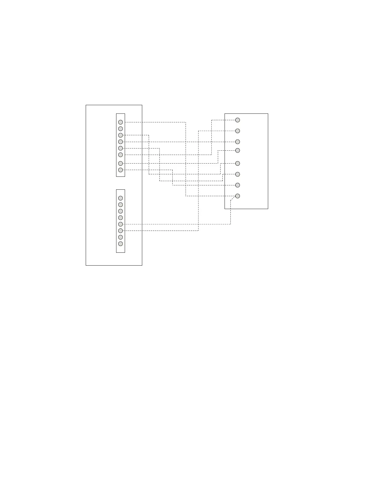
Fig. 38 — Typical Rooftop Unit with Perfect Humidity Adaptive Dehumidification System and Programmable Thermostat
Rc
Rh
W1
G
Y2
C
O/W2/B
Y1
OAT
RRS
SRTN
HUM
D1
D2
V+
Vg
C
HUM
G
W2
W1
Y2
Y1
R
PROGRAMMABLE
THERMOSTAT
UNIT CONTROL BOARD
THERMOSTAT CONNECTIONS

 Loading...


