11
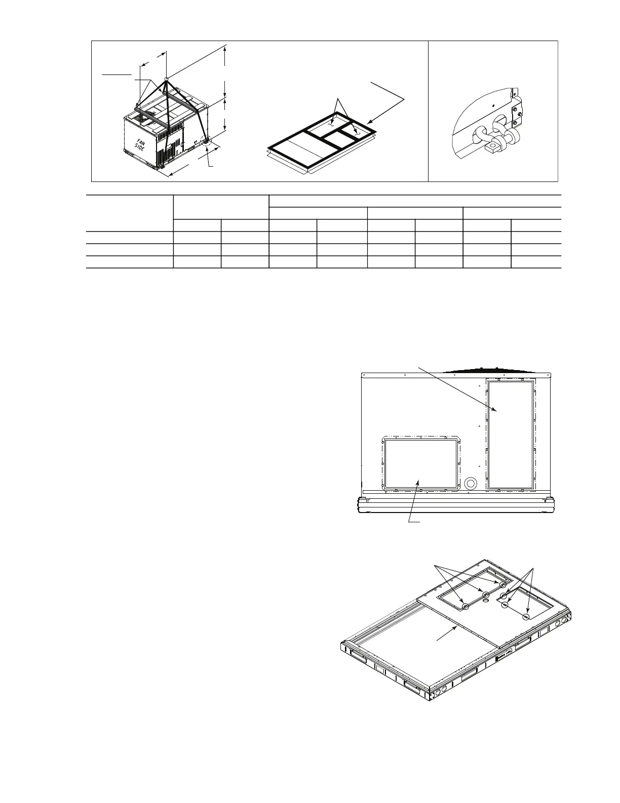
Fig. 5 — Rigging Details
Flue gas can deteriorate building materials. Orient unit such
that flue gas will not affect building materials. Locate mechan-
ical draft system flue assembly at least 48-in. (1220 mm) from
an adjacent building or combustible material. between unit and
other electrically live parts is 48-in. (1220 mm).
NOTE: Installation of accessory flue discharge deflector kit will
reduce the minimum clearance to combustible material to 18-in.
(460 mm).
After unit is in position, remove rigging skids and shipping
materials.
Step 7 — Convert to Horizontal and Connect
Ductwork (When Required)
Unit is shipped in the vertical duct configuration. Unit without
factory-installed economizer or return-air smoke detector option
may be field-converted to horizontal ducted configuration. To
convert to horizontal configuration, remove screws from side duct
opening covers (see Fig. 6) and remove covers. Use the screws to
install the covers on vertical duct openings with the insulation-side
down. The panels must be inserted into the notches on the basepan
to properly seal. The notches are covered by the tape used to
secure the insulation to the basepan and are not easily seen. See
Fig. 7 for position of the notches in the basepan. Seals around duct
openings must be tight. Secure with screws as shown in Fig. 8.
Cover seams with foil duct tape.
Field-supplied flanges should be attached to horizontal duct
openings and all ductwork should be secured to the flanges.
Insulate and weatherproof all external ductwork, joints, and roof
or building openings with counter flashing and mastic in
accordance with applicable codes.
Do not cover or obscure visibility to the unit’s informative data
plate when insulating horizontal ductwork.
Fig. 6 — Horizontal Conversion Panels
Fig. 7 — Location of Notches
DETAIL "A"
PLACE ALL SEAL STRIP IN PLACE
BEFORE PLACING UNIT ON ROOF CURB.
DUCT END
SEE DETAIL "A"
"A"
(914-1371)
36"- 54"
"C"
"B"
SPREADER
BARS
REQUIRED
NOTES:
1. SPREADER BARS ARE REQUIRED. Top damage will occur if spreader bars are not used.
2. Dimensions in () are in millimeters.
3. Hook rigging shackles through holes in base rail, as shown in Detail A. Holes in base rails are centered around the unit center of
gravity. Use wooden top to prevent rigging straps from damaging unit.
UNIT
MAX WEIGHT
DIMENSIONS
A B C
lb kg in. mm in. mm in. mm
581K*04F 815 370 74.5 1890 36.5 925 33.5 850
581K*05F 902 409 74.5 1890 36.5 925 33.5 850
581K*06F 1008 457 74.5 1890 36.0 915 41.5 1055
REMOVABLE HORIZONTAL
SUPPLY DUCT OPENING COVER
REMOVABLE HORIZONTAL
RETURN DUCT OPENING COVER
BASEPAN
NOTCHES
NOTCHES

 Loading...


