14
Install a gas supply line that runs to the unit heating section.
Refer to the NFPA 54/NFGC or equivalent code for gas pipe
sizing data. Do not use a pipe size smaller than
1
/
2
-in. Size the
gas supply line to allow for a maximum pressure drop of
0.5 in. wg (124 Pa) between gas regulator source and unit gas
valve connection when unit is operating at high-fire flow rate.
The gas supply line can approach the unit in three ways: hori-
zontally from outside the unit (across the roof), thru-curb/under
unit basepan (accessory kit required), or through unit basepan
(factory option or accessory kit required). Consult accessory
kit installation instructions for details on these installation
methods. Observe clearance to gas line components per
Fig. 16.
Fig. 16 — Gas Piping Guide
(with Accessory Thru-the-Curb Service Connections)
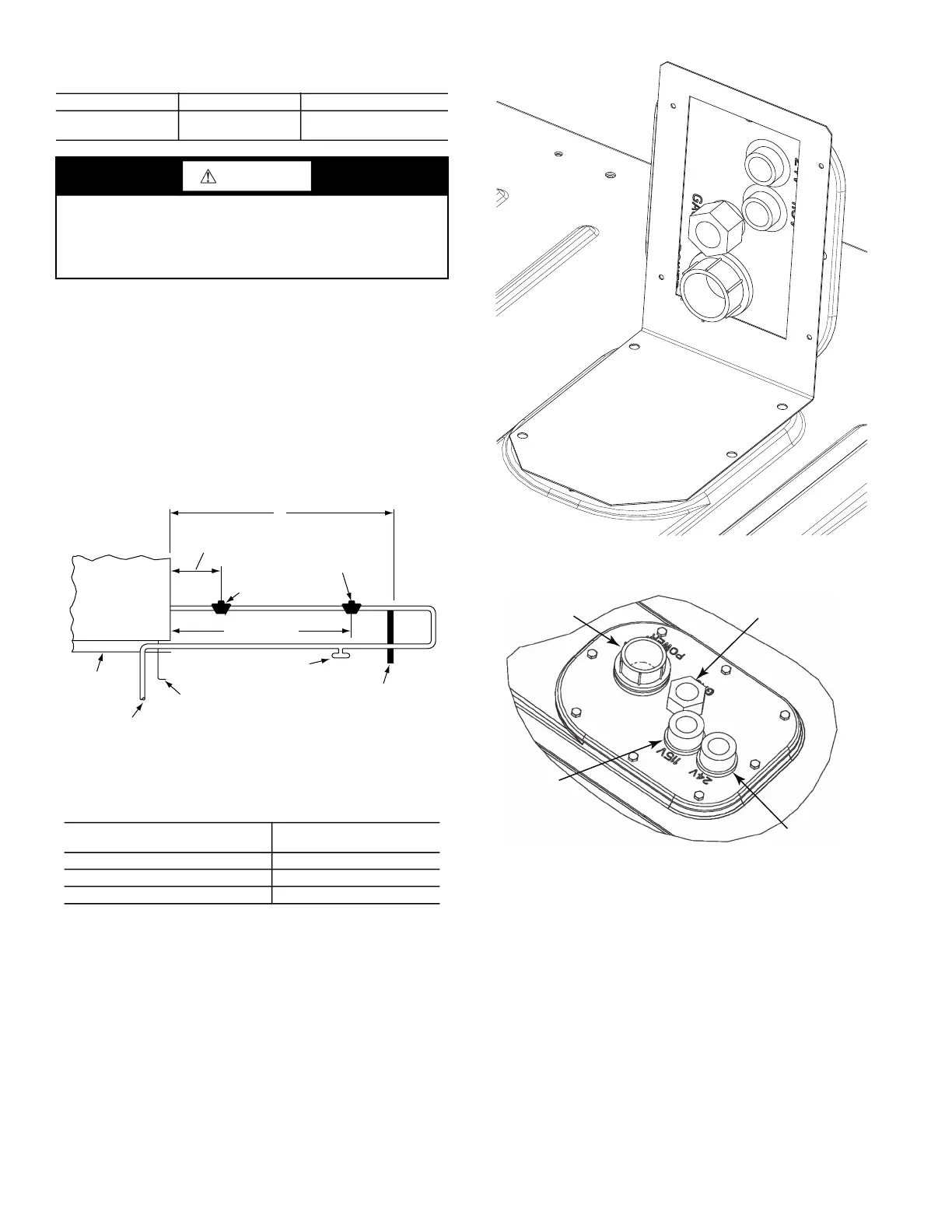
FACTORY OPTION THRU-BASE CONNECTIONS (GAS
CONNECTIONS)
This service connection kit consists of a 1/2-in. electrical bulkhead
connector and a 3/4-in. electrical bulkhead connector, connected
to an “L” bracket covering the embossed (raised) section of the
unit basepan in the condenser section (see Fig. 17 for shipping
position).
The 3/4-in. bulkhead connector enables the low-voltage control
wires to pass through the basepan. The 1/2-in. bulkhead connector
allows the high-voltage power wires to pass through the basepan.
See Fig. 18.
Fig. 17 — Thru-the-Base Fitting Assembly (Shown in
Shipping Position)
Fig. 18 — Thru-Base Connection Fittings
1. Remove the “L” bracket assembly from the unit.
2. Remove connector plate assembly from the “L” bracket
and discard the “L” bracket, but retain the washer head
screws and the gasket (located between the “L” bracket
and the connector plate assembly).
NOTE: Take care not to damage the gasket, as it is reused in the
following step.
3. Place the gasket over the embossed area in the basepan,
aligning the holes in the gasket to the holes in the basepan.
See Fig. 18.
4. Install the connector plate assembly to the basepan using 8
of the washer head screws.
The thru-base gas connector has male and female threads. The
male threads protrude above the basepan of the unit; the female
threads protrude below the basepan.
Table 4 — Natural Gas Manifold Pressure
UNIT MODEL UNIT SIZE MANIFOLD PRESSURE
581K*--F 04, 05, 06
3.2 in. wg
(797 Pa)
CAUTION
EQUIPMENT DAMAGE
Failure to follow this caution may result in equipment damage.
When connecting the gas line to the unit gas valve, the installer
MUST use a backup wrench to prevent damage to the valve.
X
BASE UNIT
BASE RAIL
ROOF
CURB
9” MINIMUM CLEARANCE
FOR PANEL REMOVAL
MANUAL GAS
SHUTOFF VALVE
*
GAS
REGULATOR
*
48” MINIMUM
DRIP LEG
PER NFGC
*
FIELD-FABRICATED
SUPPORT
*
FROM
GAS
METER
LEGEND *Field supplied.
NFGC —
National Fuel Gas
Code
NOTE: Follow all local codes.
STEEL PIPE
NOMINAL DIAMETERS (IN.)
SPACING OF SUPPORTS
X DIMENSION (FT)
1
/
2
6
3
/
4
or 1 8
1
1
/
4
or larger 10
LOW VOLTAGE
CONDUIT
CONNECTOR
HIGH VOLTAGE
CONDUIT
CONNECTOR
BRASS FITTING FOR
3 TO 6 TON UNITS
AUXILIARY
POWER
SUPPLY
(OPTIONAL)

 Loading...


