15
Check tightness of connector lock nuts before connecting gas
piping.
Install a
1
/
2
-in. NPT street elbow on the thru-base gas fitting.
Attach a
1
/
2
-in. pipe nipple with minimum length of 16-in.
(406 mm) (field-supplied) to the street elbow and extend it
through the access panel at the gas support bracket. See
Fig. 19.
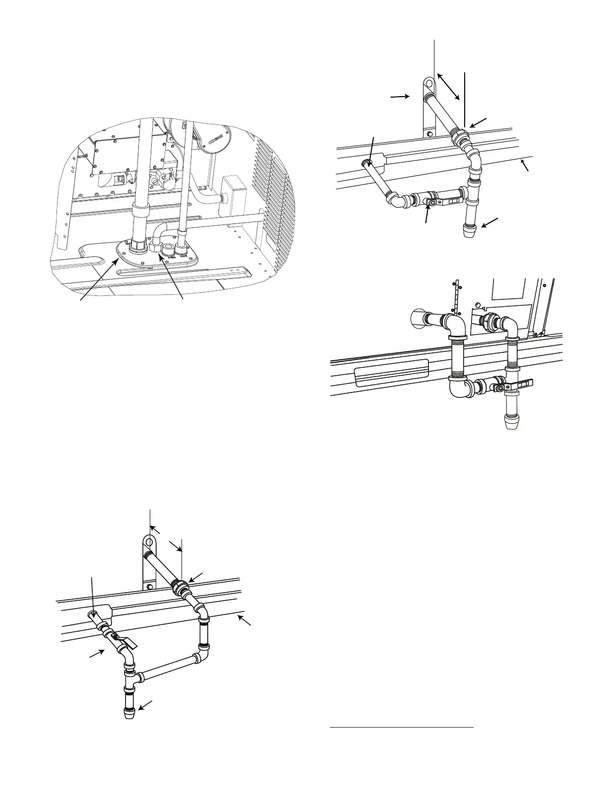
Fig. 19 — Gas Line Piping
Other hardware required to complete the installation of the gas
supply line includes a manual shutoff valve, a sediment trap
(drip leg) and a ground-joint union. A pressure regulator valve
may also be required (to convert gas pressure from pounds to
inches of pressure). The manual shutoff valve must be located
within 6 ft (1.83 m) of the unit. The union, located in the final
leg entering the unit, must be located at least 9-in. (230 mm)
away from the access panel to permit the panel to be removed
for service. If a regulator valve is installed, it must be located a
minimum of 4 ft (1220 mm) away from the unit’s flue outlet.
Some municipal codes require that the manual shutoff valve be
located upstream of the sediment trap. See Fig. 20 and 21 for
typical piping arrangements for gas piping that has been routed
through the sidewall of the curb. See Fig. 22 for typical piping
arrangement when thru-base is used. Ensure that all piping
does not block access to the unit’s main control box or limit the
required working space in front of the control box.
Fig. 20 — Gas Piping, Typical Curb Sidewall Piping
(Example 1)
Fig. 21 — Gas Piping, Typical Curb Sidewall Piping
(Example 2)
Fig. 22 — Gas Piping, Typical Thru-Base Connections
When installing the gas supply line, observe local codes per-
taining to gas pipe installations. Refer to the NFPA 54/ANSI
Z223.1 NFGC latest edition (in Canada, CAN/CSA B149.1).
In the absence of local building codes, adhere to the following
pertinent recommendations:
• Avoid low spots in long runs of pipe. Grade all pipe
1
/
4
-in.
per every 15 ft (7 mm per every 5 m) to prevent traps.
Grade all horizontal runs downward to risers. Use risers to
connect to heating section and to meter.
• Protect all segments of piping system against physical and
thermal damage. Support all piping with appropriate
straps, hangers, etc. Use a minimum of one hanger every
6 ft (1.8 m). For pipe sizes larger than
1
/
2
-in., follow rec-
ommendations of national codes.
• Apply joint compound (pipe dope) sparingly and only to
male threads of joint when making pipe connections. Use
only pipe dope that is resistant to action of liquefied petro-
leum gases as specified by local and/or national codes. If
using PTFE (Teflon
1
) tape, ensure the material is Double
Density type and is labeled for use on gas lines. Apply tape
per manufacturer’s instructions.
• Pressure-test all gas piping in accordance with local and
national plumbing and gas codes before connecting piping
to unit.
NOTE: Pressure test the gas supply system after the gas supply
piping is connected to the gas valve. The supply piping must be
BRASS FITTING FOR GAS PIPINGEMBOSSMENT
9” (229mm) MIN
UNION
SHUT OFF
VALVE
DRIP
LEG
THRU-CURB ADAPTER
UNIT BASE RAIL
1. Teflon is a registered trademark of DuPont.
SHUT OFF
VALVE
UNION
9” (229 mm) MIN
UNIT BASE RAIL
BURNER
ACCESS
PANEL
THRU-CURB ADAPTER
DRIP
LEG

 Loading...


