EasyManuals Logo

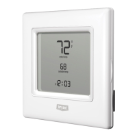
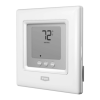
Bryant Preferred T6-PAC01-A Installation Instructions

Bryant Preferred T6-PAC01-A
68 pages
To Next Page IconTo Next Page
To Previous Page IconTo Previous Page
Page #50 background imageLoading...
Page #50 background image
48
Table 3 Equipment Configuration Outputs
For COOL, HEAT and Emergency Heat modes, the following chart shows the state
for each output in each stage of operation
Equip
Config
Tstat
Model
COOL
STG 1
COOL
STG 2
HEAT
STG 1
HEAT
STG 2
HEAT
STG 3
HEAT
STG 4
EM HEAT
STG 1
EM HEAT
STG 2
SS AC
Opt 1 =
AC
T6-PAC01-A
T6-NAC01-A
Y/Y2 -- W/W1 -- -- -- -- --
SS AC
Opt 1 = AC
T6-PHP01-A
T6-NHP01-A
Y/Y2 -- W/W1
W/W1
O/W2/B
(if Opt.
32 = 2)
-- -- -- --
SS HP
Opt 1 = HP
RVS = O
Opt 10 = C
T6-PHP01-A
T6-NHP01-A
Y/Y2,
O/W2/
B
-- Y/Y2
Y/Y2,
W/W1
Y/Y2
W/W1
--
W/W
1
W/W1
Y1/W2
SS HP
Opt 1 = HP
RVS = B
Opt 10 = H
T6-PHP01-A
T6-NHP01-A
Y/Y2 --
Y/Y2,
O/W2/
B
Y/Y2,
W/W1,
O/W2/
B
Y/Y2,
W/W1,
Y1/W2,
O/W2/B
--
W/W
1
W/W1
Y1/W2
2SPD AC
Opt 1 =
A2
T6-PHP01-A
T6-NHP01-A
Y1/W2
Y/Y2,
Y1/W
2
W/W1
W/W1
O/W2/
B
-- -- -- --
2SPD HP
Opt 1 =
H2
RVS = O
Opt 10 =
C
T6-PHP01-A
T6-NHP01-A
Y1/W2,
O/W2/
B
Y1/W2
Y/Y2
O/W2/B
Y1/W
2
Y1/W2
Y/Y2
Y1/W2,
Y/Y2,
W/W1
--
W/W
1
--

Other manuals for Bryant Preferred T6-PAC01-A

Questions and Answers:

Question and Answer IconNeed help?

Do you have a question about the Bryant Preferred T6-PAC01-A and is the answer not in the manual?

Bryant Preferred T6-PAC01-A Specifications

General IconGeneral
BrandBryant
ModelPreferred T6-PAC01-A
CategoryThermostat
LanguageEnglish

Related product manuals