should
be st€adied
to
prevent possible
damage. Whetr the
barrel
is remov€d,
cover the mouth of
the
craokcåse
with
rag to
prevent
rust and
gdt
falling
in. To reftove
the
piston
from
the connecting rod
it is
first
necessary to
take
out
one of
the
gudgeon pin
circlips.
This is best ac.om-
plished
with
a
pointed
instrument such as the tang
of
a
file suitably
ground.
Before the
gudgeon pin
can be withdrawn
it may be
necessary,
jf
the engine is cold,
to
heat
the
piston
with the
aid of rags
imme6ed in hot water,
wrung out, and held
round tlle
piston.
Then, supporting
the
piston,
tap
tbe
gudgeon
pin
through using
a light hammer and a
punch.
When the
piston
is free,
mark the inside of the
piston
skfut at th6 back,
so that it can be
replaced the corect
way rouod.
If the rings
are stuck in
the
grooves gleat
care will be
treeded to
pdse
them free and to
lemove them from the
piston.
All carbon
deposit should be
carefully scraped
from
the
grooves
and the
inside
edges
of the rings. If
eithe. of
the rings shows
brown
patches
on the face,
replace
with a new
qg.
Check
the
piston
ng
gap
by inserting
the
piston
in
the barrel
and sliding
each ling indcpendently
up to the
skiit
ofthe
piston,
check the
gap
with feeler
gauges,
and
this should
not
be
less than .008
in.
or
morc than .012 in.
Fit
new rings
if the
gap greatly
exoeeds the figure stated,
although
a few
thousandths of an
inch extra
gap
are not
serious. It
is advisable
to check the
gap
of new
dngs
before fitting,
and if the
gap
is less than .008 in, the
ends
of
the rings
should be carefully
filed to the corect
limit.
It
should be
noted that
piston
rings
are very britde,
and unless handled
carcfully a.e
easily broken. This
appties
palticula
y
to the søaper ring.
Re€ssembling.
When
the lings arc
refitted, replace the
piston
on tho connecting
rod
(see
that
it is the
right
way
round), smeår
the
gudgeon
pin
libe(ally with engine oil,
add
tap
into
position.
Then
refit the
Sudgeon
pin
circ[p.
Smear
the
pistor
liberally
witl clean eDgine oil; turn
thc dngs.
so that
tho
gaps
are on opposite sides of the
pistoo;
fit a ncrf, cylinda!
base washer on
the
cmnkcase;
liberElly c.at the inride
of the cylhder barrel wirh
clean
engine oil
aDd then, coEplessing the rings in
tum by
hand,
carefully slide the baEel i[to
position
over rhe
piston.
This operation will
be simplified if the
piston
rings ar€ compressed into their
grooves
by means of metal
bands, such as can be obtained from
accessory suppliers.
Next replace the valves into
their
respective
positions,
place
the springs over the stems
with the top collar iD
porition,
and with l,he head rsting on
wooden block
as
befor€, compress the springs until the split
collets can
be
inserted. A dab of
grease
on the inside
of the collets will
serve
to hold them in
position
u.til the spring is released.
Make
quite
sure that the
collets are corlectly located,
(For
Comp. and
Gold Star models see
pages
49
and 5l
respectively).
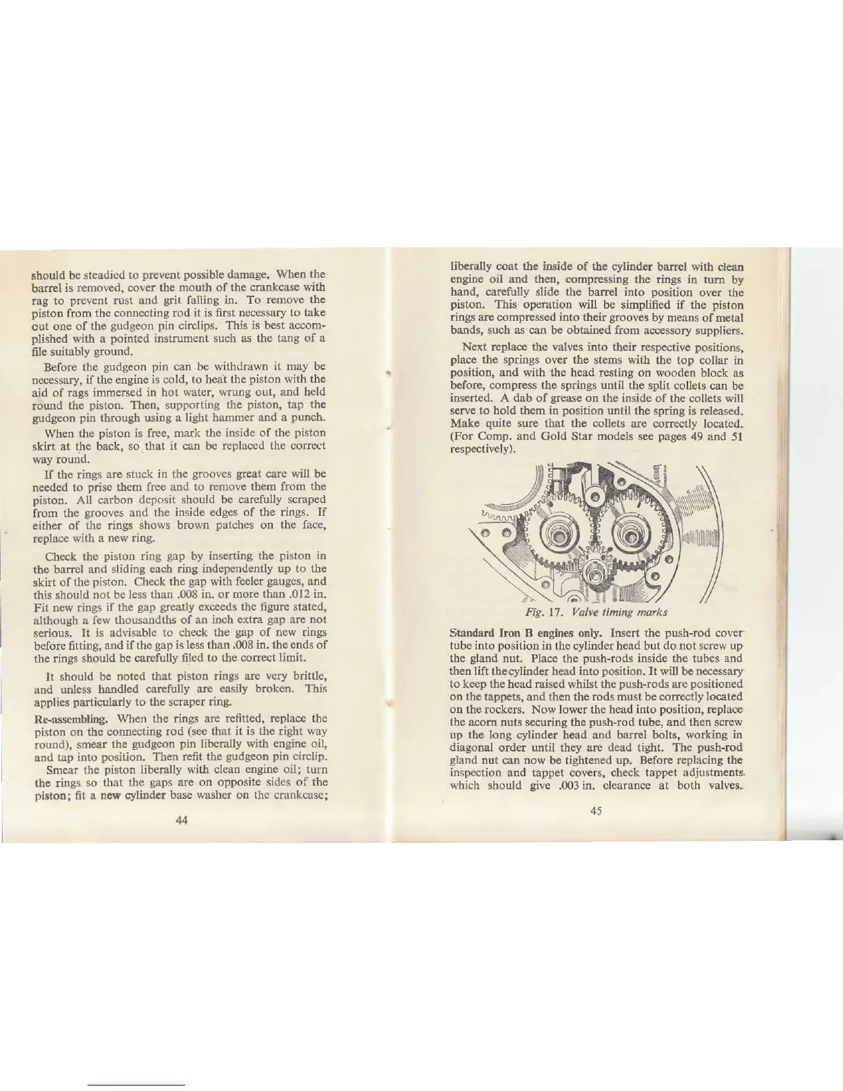
ng. 17. Valw
timing ,narks
Standard
kon B engines or
y.
Insert
the
push-rod
cover
tube into
position
iD
tho oylinder head
but do not screw up
the
gland
nut.
Place the
push-rods
inside the tubes
and
then lift the
cylinder
head into
position.
It will
be
necessary
to ke€p the head raised
whilst
the
push-rods
are
positioned
on the tappets, atrd then the rods must be corectly located
oq the rocke$. Now lorrer the head into
position,
rcplacc
the
acom nuts secudn8 the
push-rod
tube, add then screw
up the long
cylinder head and barrel bolts,
working in
diagonal orde! until
they
are deåd tight. The
push-rod
gland
Dut
can
dow
be tightened
up. Before replacing the
inspection
and tappet covers, check
tappet adjustments.
which should
give
.@3
in. clearance at both valves.
i
I
ij
I
I
I