When DC or AC voltage measurement has been completed,
disconnect the connection between the testing lead and the circuit
5-2. Resistance measurement
The resistance range are: 200.0Ω, 2.000KΩ,20.00KΩ, 200.0KΩ ,
To measure resistance, connect the meter as follows:
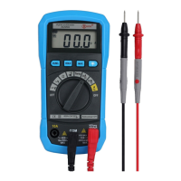
① Insert the red test lead into the ”VΩ” terminal and the black
test lead into the COM terminal.
② Set the rotary switch to proper resistance range..
③ Connect the test lead across with the object under testing.
The measured value will be show on the LCD display.
●
The test lead can add 0.1Ω to 0.2Ω of error to resistance
measurement. To obtain precision reading in low-resistance
measurement, that is the range of 200.0Ω, short the input
terminal before measuring. In this time, the contact
resistance displayed on the LCD.You can subtract the contact
resistance value from the measured value.
●
For high-resistance measurement (>10MΩ), it is normal
taking several second to obtain stable reading.
● The LCD display “OL” indicating open-circuit for the tested
resistor or the resistor value is higher than the maximum
5-3. Diode/Continuity check
① Set the rotary switch to “ ” position. First time, default
mode is diode check mode.You can enter the continuity check
② insert the red test lead into the “VΩ” terminal and the black test
lead into the “COM” terminal.