Do you have a question about the btsr SMART 64 H and is the answer not in the manual?
Guide on how to effectively use the operation manual and understand its structure.
Explanation of the various symbols and icons used throughout the manual for clarity.
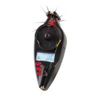
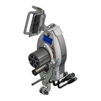
Details the physical components of the SMART 64 H / 200 K system, including terminal and sensors.
Explains how the system's sensors and terminal function together for yarn control.
Highlights unique capabilities like flexibility, simplicity, and precision of the system.
Overview of general features across BTSR systems, including self-learning and sensor technology.
Provides specifications for the SMART 64 H / 200 K terminal and IS3.. sensors.
Instructions and considerations for correctly installing the SMART system.
Diagrams and explanations for connecting system components and power.
Illustrates a typical wiring setup for connecting the SMART system to circular knitting machines.
Lists and describes various BTSR cables and power supply units for system installation.
Details the methods for external system reset, either via push button or automatic trigger.
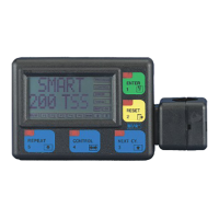
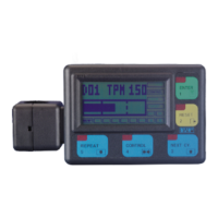
Describes the terminal's control panel, buttons, LEDs, and display layout.
Explains the functions of the ENTER and RESET buttons for navigation and confirmation.
Explains the functions of NEXT CY, CONTROL, and REPEAT buttons for system operation.
Defines the operational status indicated by the red LEDs on the terminal's function buttons.
Describes the terminal's display area for messages, settings, and status indicators.
Details the capabilities, features, types, and installation of IS3.. yarn control sensors.
Provides steps for installing IS3.. sensors and interpreting their LED signaling.
Details how sensor detection is influenced by various settings and yarn characteristics.
Defines and explains the programming of F_START and F_STOP parameters for yarn detection.
Explains SENS for sensitivity adjustment and DELAY for reaction time configuration.
Covers initial checks, operating sequences, and activating the learning cycle.
Explains control phase messages and provides a summary diagram of the configuration menu.
Details the P1 level functions, including SYNC, ZERO, PHASE, DEVICES, and passwords.
Explains P2 and P3 levels for global and individual yarn error tolerance settings.
Details P4 and P5 levels for configuring global and individual sensor sensitivity and reaction time.
Covers sensor and communication tests, and PX level for frequency and speed settings.
Describes setting production targets, reading counters, and machine stop conditions.
Details how to view and reset error counts for broken and uncut yarns.
Provides solutions for common faults, error messages, and system issues.
Procedure to temporarily disable a faulty sensor to prevent machine stops.
Guides through testing system functionality and outlines ordinary maintenance and repair guidelines.
Step-by-step instructions for updating the terminal's software version.
A table to record and restore system configuration settings for future reference.
Flowchart summary for setting production targets and resetting counters.
Flowchart summary for reading production counts and adjusting rejected items.
Illustrates programming flow for various menu levels (P1-PX) and TEST functions.
Flowchart summary for accessing and resetting BROKE/UNCUT error counters.
Wiring diagram specific to connecting the SMART system on large circular knitting machines.
Lists cables and power supply devices compatible with the SMART 200 K system.
Describes external reset methods for the SMART 200 K terminal.
Covers initial checks and procedures for operating the SMART 200 K terminal.
Explains control phase messages specific to the SMART 200 K system.
Details ZERO parameter and REPEAT mode for SMART 200 K, including circularity settings.
A summary table for configuration values, highlighting differences for SMART 200 K.
Illustrates P1 menu programming flow, noting differences for SMART 200 K.
| Power Supply | 24 VDC |
|---|---|
| Display | LCD |
| Mounting | DIN Rail |
| Output Signal | 4-20 mA |
| Communication Interface | RS485 |
| Operating Temperature | 0 to 50°C |
| Storage Temperature | -20 to 70°C |