Do you have a question about the btsr TS5 Series and is the answer not in the manual?
Explains the manual's structure, divided into chapters and appendix for system operation.
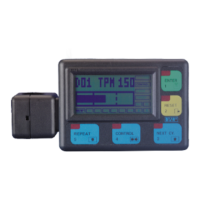
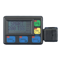
Describes the SMART 200 TSS terminal and the TS5.. sensors that comprise the system.
Explains how TS5.. sensors measure and analyze yarn tension for quality control.
Highlights the system's flexibility, simplicity, and parametric nature for yarn quality control.
Details features like TS5.. sensors, automatic numbering, programmable functions, and easy monitoring.
Lists specifications for the SMART 200 TSS Terminal and TS5.. Sensors.
Provides guidance on connecting sensors to the terminal and power supply.
Diagrams and pinouts for SMART 200 TSS terminal connections.
Illustrates wiring for TSS applications on specific textile machines.
Illustrates wiring for TSQ applications on specific textile machines.
Lists available cables, connectors, transformers, and power supplies.
Describes the terminal's buttons, display, and operator guidance.
Explains icons and symbols used throughout the manual.
Explains how display case indicates active choices and alternatives.
Explains the display area for messages, selections, and graphical data.
Details the labels indicating system status and menu hierarchy levels.
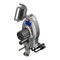
Describes the intelligent TS5.. sensors for yarn tension detection.
Explains how sensors detect defects, stop the machine, and signal status.
Details sensor coding rules and eyelet models available.
Provides dimensions and diagrams of the TS5.. sensor.
Shows pin assignments for TS5.. sensor connectors.
Illustrates recommended mounting orientations for TS5.. sensors.
Details signals used by TS5.. sensors for communication.
Explains the operation and characteristics of the STOP output signal.
Describes the function and signal behavior of the ENABLE input.
Explains the meaning of Green and Red LEDs on TS5.. sensors.
Lists parameters like TENS, PEAK, NOYARN that influence detection.
Defines TENS as the setpoint for tension threshold calculations.
Explains TENS H as the upper limit for tension threshold detection.
Defines TENS L as the lower limit for tension threshold detection.
Explains PEAK H as the upper limit for tension peak detection.
Defines PEAK L as the lower limit for tension peak detection.
Describes the parameter for detecting missing or broken yarn.
Lists factors like DELAY CONTROL, LOCK/UNLOCK, MONITOR/CONTROL, STOP NO/NC.
Configures sensor entry delay time before entering control status.
Manages Touch Light button operation for reset and numbering.
Sets system operation for defect detection in MONITOR or CONTROL mode.
Defines the operating mode of the STOP output as Normally Open or Closed.
Configures the ENABLE input mode as Normally Open or Closed.
Selects Absolute or Relative mode for sensor data calculation.
Outlines initial checks and procedures before using the system.
Lists the main functions and operating sequences of the system.
Details initial commissioning steps for TS5.. sensors.
Guides through configuring system parameters via the SETUP menu.
Covers creating, modifying, and erasing articles in the system.
Explains how to load/unload articles and scan sensor data.
Details how to access and use the graphical display functions.
Describes running system monitoring and fault counters in CONTROL mode.
Guides through global automatic numbering of sensors.
Explains how to number, replace, or add individual sensors.
Allows logical subdivision of the machine into sides A and B.
Configures the system's operating mode as TSS or TSQ.
Sets system operation mode (Monitor or Control) upon failure detection.
Enables or disables Touch Light button for alarm reset.
Configures the STOP output signal as Normally Open or Normally Closed.
Configures the ENABLE input signal as Normally Open or Normally Closed.
Sets the delay time before sensors enter the CONTROL status.
Adjusts sensor offset to correct for environmental shifts or yarn absence.
Selects Absolute or Relative mode for sensor data calculation.
Sets a password to access SETUP and WORK menus.
Sets a password to access the LEARN function.
Reads and sets the date and time for production reports.
Checks communication between terminal and individual sensors.
Tests the communication line efficiency between terminal and sensors.
Checks and updates software versions on individual sensors.
Guides on creating new articles and setting quality control parameters.
Sets the reference nominal tension (setpoint) for a new article.
Configures parameters for "Max Tension Threshold Exceeded" failure.
Configures parameters for "Min Tension Threshold Exceeded" failure.
Configures parameters for "Max Tension Peak Exceeded" failure.
Configures parameters for "Min Tension Peak Exceeded" failure.
Configures parameters for the Yarn Missing failure.
Allows modification of parameters for previously created articles.
Removes articles from the database.
Shows articles currently loaded into the sensors.
Loads article settings onto a specified range of sensors.
Removes previously loaded articles from sensor memory.
Displays real-time tension detected by individual TS5.. sensors.
Compares tensions detected by multiple sensors using histograms.
Guides through the learning cycle for TSQ mode.
Prints a summary of fault counters for machine positions.
Shows an example of the output from the production report function.
Lists common faults, causes, and solutions for the system.
Provides guidance on periodic cleaning of sensors and terminal.
States that repairs must be performed by specialized BTSR personnel.
Step-by-step guide for updating terminal software.
Tables for noting down article parameters for easier configuration.
Quick reference flow chart for initial sensor configuration.
Quick reference flow chart for defining machine sides.
Quick reference for configuring TSS/TSQ modes.
Quick reference for setting Monitor or Control mode.
Quick reference for enabling/disabling the Touch Light button.
Quick reference for STOP signal NO/NC configuration.
Quick reference for ENABLE signal NO/NC configuration.
Quick reference for setting sensor delay time.
Quick reference for sensor offset configuration.
Quick reference for selecting sensor operating mode.
Quick reference for setting SETUP menu access password.
Quick reference for setting LEARN function access password.
Quick reference for setting printer clock and calendar.
Quick reference for testing sensor communication.
Quick reference for testing communication line efficiency.
Quick reference for testing and updating sensor software versions.
Quick reference flow chart for creating new articles.
Quick reference flow chart for modifying existing articles.
Quick reference flow chart for erasing articles.
Quick reference flow chart for loading articles onto sensors.
Quick reference flow chart for unloading articles from sensors.
Quick reference flow chart for scanning loaded articles.
Quick reference for visualizing tension per device.
Quick reference for comparing tensions of multiple devices.
| Series | TS5 |
|---|---|
| Category | Control Systems |
| Power Supply | 24 VDC |
| Protection Class | IP20 |
| Communication Interface | RS485 |