Do you have a question about the btsr SMART MATRIX WARP and is the answer not in the manual?
Diagram showing interconnections among SMART MATRIX terminal, SM-DIN boards, and PC.
Shows connection of IS3 Sensors and Lamp Interface Modules (ACT/D) to SM-DIN Boards.
Electrical interface (pin assignment) of SM-DIN Warp Board.
Electrical interface (pin assignment) of SM-DIN to sensors connection.
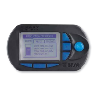
Overview of operation and interface of the SMART MATRIX WARP control terminal.
Describes the navigation technique using the Rotary Selector for parameter settings.
Process for uniquely identifying connected sensors and defining the creel structure.
Configuring user names, passwords, and access rights to menus and options.
Checking communication efficiency between SMART MATRIX, SM-DIN Boards, and sensors.
Calibrating (offsetting) TS5/TS7 sensors.
Classification and description of error and failure messages from the system.
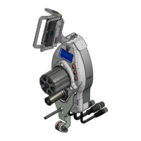
Details on the capabilities, optical interface, and signaling lights of IS3 sensors.
Information on TS5/TS7 sensor functionality, operation, and signaling lights.
Comparison of TS5 and TS7 sensors, focusing on electrical interface and technical characteristics.
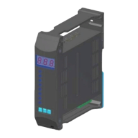
Describes the SM-DIN WARP Boards as the interface between sensors and the SMART MATRIX terminal.
Defining logical arrays for sensor identification based on machine configuration.
Programming two sets of control parameters (SLOW/FAST) and automatic switching.
| Brand | btsr |
|---|---|
| Model | SMART MATRIX WARP |
| Category | Control Systems |
| Language | English |