SM-DIN ↔ ACT/Ds ↔ Machine Interface
SMART MATRIX - 1-7 -
SM-DIN ↔ ACT/Ds ↔ Machine Interface
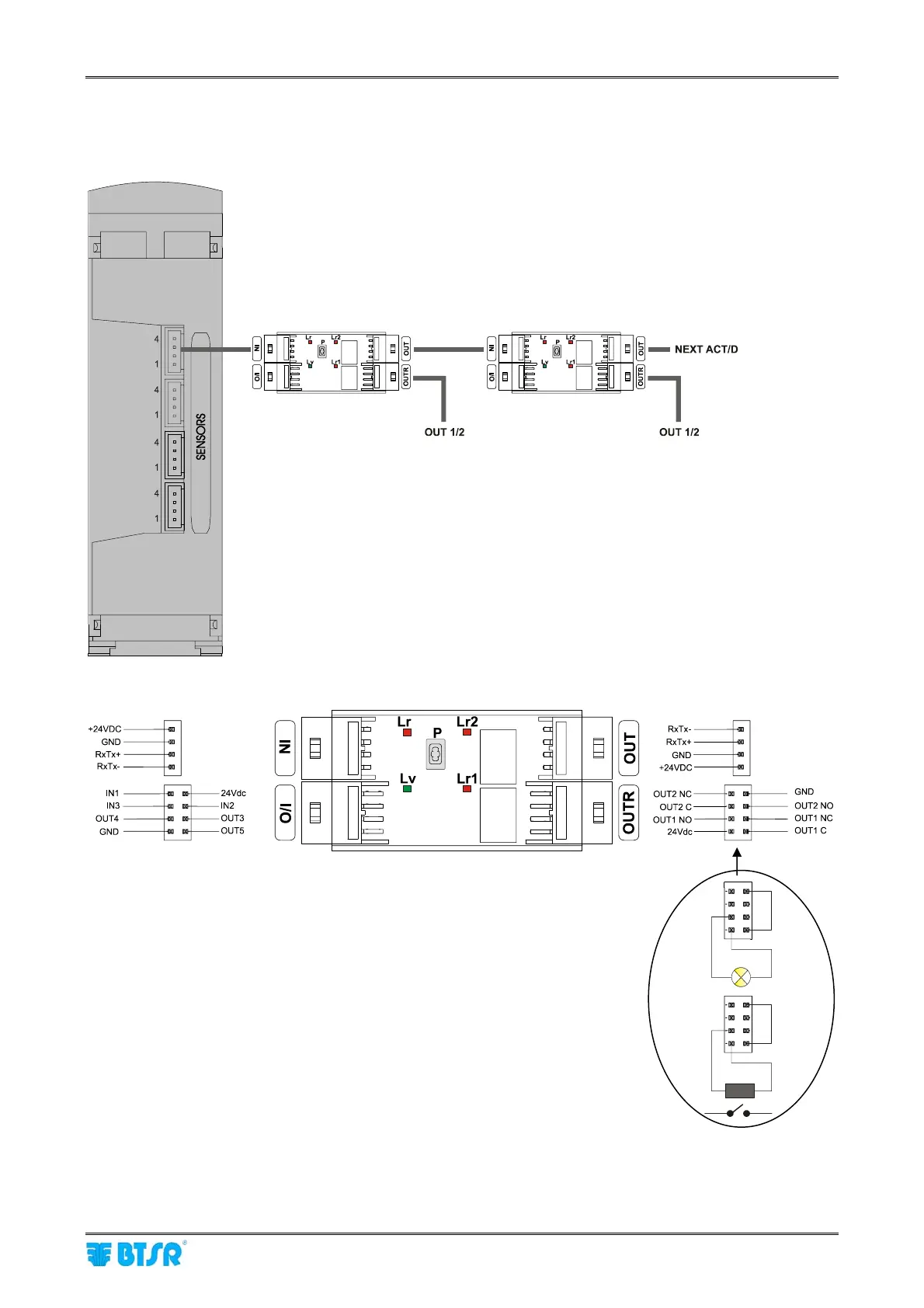
The following diagram shows the electrical interface (pin assignment) of ACT/D modules.
P = Numbering button
Lv = Green Led (normally flashing)
Lr = Red Led (on = communication with SM-DIN in progress)
Lr1 = Red Led (on = out 1 active)
Lr2 = Red Led (on = out 2 active)
IN X = Inputs not used for Warp application
The outputs of ACT/D modules will always be indicated (for simplification)
as “Lamps”.
(1) Lamp direct connection example (I
max
= 100 mA) as NO contact.
(2) Lamp connection example by means of external relay (I> 100 mA).
- Lamp/Cutter, etc. -
- Lamp/Cutter, etc. -
(1)
(2)