EasyManua.ls Logo

btsr WINDINGFEEDER - User Manual

Default Icon
47 pages
Print Icon
To Next Page IconTo Next Page
Loading...
WINDINGFEEDER
YARN CONTROL SYSTEM
Operating Manual
ENGLISH
Rev. 2.0 – -March 2011

Table of Contents

Questions and Answers

  • S
    Samuel HenryAug 18, 2025
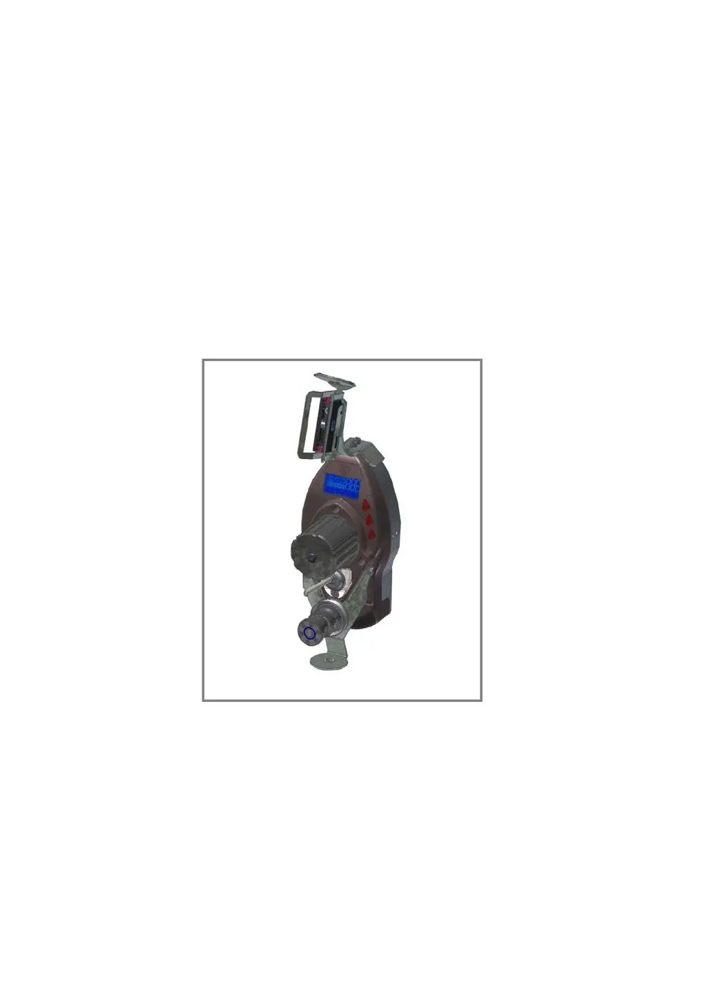
    Why is the machine not stopped by the btsr WINDINGFEEDER Control Systems device when the yarn breaks?
    • E
      Emily OwenAug 18, 2025
      The machine may not stop due to the de-activation of the third parameter of the P1 programming level or a wiring problem. Ensure the correct programming of WINDINGFEEDER parameters and check the connection of P1-P2 inputs. If the red LEDs on the WINDINGFEEDER device light up when the yarn breaks, verify the machine connections.
  • M
    Mary WestAug 20, 2025
    What to do if E2 is displayed on my btsr WINDINGFEEDER Control Systems display?
    • S
      Sarah StaffordAug 20, 2025
      If 'E2' appears on the WINDINGFEEDER display, it could be due to a locked motor or temporary triggering of internal protections. Check if the motor is turning correctly; detach the feeding wheel to remove any yarn remnants that might be preventing the motor from turning. Ensure the WINDINGFEEDER device is correctly threaded. If the issue persists, turn the electrical supply of the device off and then on again.
  • N
    Nathan DaughertyAug 23, 2025
    What does it mean when CURRENT is displayed on my btsr WINDINGFEEDER Control Systems display?
    • S
      Scott ObrienAug 23, 2025
      If 'CURRENT' is displayed on the WINDINGFEEDER display, it means the current drawn by the device has exceeded the maximum allowed value. Check the usage conditions of the systems.
  • C
    Christopher FrazierAug 25, 2025
    How to resolve the MT-BUS error on my btsr WINDINGFEEDER Control Systems display?
    • M
      Matthew SalasAug 26, 2025
      The 'MT-BUS' error on the WINDINGFEEDER display indicates that the supply voltage is lower than 15 Vdc. Check the supply voltage.
  • D
    Donna StanleyAug 27, 2025
    What does it mean when TE is displayed on my btsr WINDINGFEEDER Control Systems display?
    • R
      Robert CollinsAug 27, 2025
      If 'TE' is displayed on the WINDINGFEEDER display, it indicates that the motor temperature of the control has exceeded the maximum expected value. Check the usage conditions of the systems.
  • S
    Stephanie TranAug 29, 2025
    How to fix a btsr WINDINGFEEDER Control Systems device that is not communicating with the SMART MATRIX FEEDER terminal?
    • R
      Randy NolanAug 30, 2025
      If the WINDINGFEEDER device isn't communicating with the SMART MATRIX FEEDER terminal, the identification code of the WINDINGFEEDER device might be incorrect, there may be a failure on the SMART MATRIX FEEDER terminal, or there could be a wiring problem. Check that the parameter corresponding to the identification number (parameter P3.4) is correct; if necessary, carry out the numbering procedure using the SMART MATRIX FEEDER terminal or set the identification code directly on the WINDINGFEEDER device (parameter P3.4). Check the overall device wiring.
  • C
    christopher68Sep 1, 2025
    What does it mean when TM is displayed on my btsr WINDINGFEEDER Control Systems display?
    • C
      Calvin SaundersSep 1, 2025
      If 'TM' is displayed on the WINDINGFEEDER display, it means the motor temperature is higher than the maximum expected value. Check the usage conditions of the systems.
  • M
    Miranda HendrixSep 3, 2025
    What to do if E3 is displayed on my btsr WINDINGFEEDER Control Systems display?
    • H
      Heather BaileySep 3, 2025
      If 'E3' is displayed on the WINDINGFEEDER display, it could be due to yarn remnants under the loading cell or an incorrectly adjusted OFFSET value. Clean the loading cell of the TS44 sensor using a light air blow (max 1 bar). Perform a correct adjustment of the OFFSET value on the WINDINGFEEDER device.
  • L
    Luis SmithSep 6, 2025
    How to fix a blank btsr WINDINGFEEDER Control Systems display?
    • I
      Isabella HarrisSep 6, 2025
      If the WINDINGFEEDER display is blank, the device may not be powered on. Check that the I/O connector is correctly plugged in and that there is a 24 Vdc power voltage on pins 1-2.
  • J
    Jennifer HaleSep 8, 2025
    What does ES ES-CONT mean on my btsr WINDINGFEEDER Control Systems display?
    • D
      Daniel RamirezSep 8, 2025
      If 'ES ES-CONT' is displayed on the WINDINGFEEDER display, it indicates an internal protection against overcurrents. Reset the alarm.

Summary

OVERVIEW OF WINDINGFEEDER

Key Device Characteristics

Outlines the primary features, technology, and capabilities of the WINDINGFEEDER devices.

Safety Guidelines and Precautions

Covers essential safety measures and considerations for operating the device.

TECHNICAL DATA AND INSTALLATION

Technical Specifications

Provides detailed specifications for the device, sensors, and terminals.

Electrical Interface and Connections

Illustrates wiring diagrams and pinouts for connecting sensors and terminals.

SMART MATRIX FEEDER Connection

Shows the specific wiring diagram for connecting the SMART MATRIX FEEDER.

Correct Yarn Threading Procedure

Provides step-by-step instructions for properly threading yarn through the device.

OPERATION OF WINDINGFEEDER DEVICES

Operator Accessible Functions

Covers simple operations like alarm reset, status checks, and device exclusion.

P1 Programming Level Parameters

Configures main tension, error tension, and time alarm settings.

Tension Error Alarm Management

Explains the generation, reset, and behavior of the "Tension Error" alarm.

WINDINGFEEDER TROUBLESHOOTING AND MAINTENANCE

LED Status Indicators

Interprets the meaning of red LED states for device identification and error conditions.

Troubleshooting Common Faults

Provides a table of faults, causes, and solutions for diagnosing issues.

btsr WINDINGFEEDER Specifications

General IconGeneral
CategoryControl Systems
ModelWINDINGFEEDER
ManufacturerBTSR
Power Supply24 VDC
Communication InterfaceRS485

Related product manuals