Do you have a question about the btsr IS3 Series and is the answer not in the manual?
Explains the structure of the operation manual and how to navigate its content.
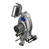
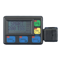
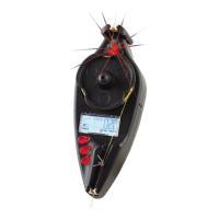
Describes the main parts of the SMART 64 H / 200 K system, including the terminal and sensors.
Explains how the system functions to monitor production and detect yarn errors.
Highlights unique features like flexibility, simplicity, and precision in yarn control.
Lists key features such as self-learning, IS3.. sensors, and programmable functions.
Covers terminal/sensor specs, installation requirements, and electrical connections.
Illustrates connection diagrams and lists required cables and power supply devices.
Explains how to use external reset signals for system control.
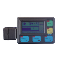
Describes the terminal's buttons, display zones, and LED indicators.
Details the capabilities, technology, and signaling lights of IS3.. sensors.
Discusses factors affecting detection and key programmable variables like F_START, F_STOP, SENS, DELAY.
Outlines initial checks and startup procedures for the system.
Lists main functions, including activating learning cycles and control phases.
Shows messages displayed during system control and error states.
Provides a summary diagram of the system's programming menu structure.
Allows setting production targets and reading/resetting production and error counters.
Lists common faults, their causes, and solutions for system issues.
Addresses issues like faulty sensors, signal errors, and temporary disabling.
Details machine test procedures and routine cleaning for sensors and terminal.
States repair policy and provides instructions for software version updates.
Flowcharts for setting targets and managing production/error counters.
Flowcharts illustrating sequences for various programming menus (P1-PX, TEST).
Illustrates connection differences and lists cables/power devices for SMART 200 K.
Covers startup, messages, ZERO, REPEAT, RESET functions, and parameter tables for SMART 200 K.
| Brand | btsr |
|---|---|
| Model | IS3 Series |
| Category | Control Systems |
| Language | English |