Do you have a question about the btsr SMART CLEARER and is the answer not in the manual?
Guide on how to effectively use the operation manual.
Explanation of symbols and their meanings throughout the manual.
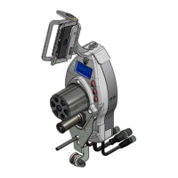
Describes the constituent parts of the SMART CLEARER system.
Explains the fundamental working principles of the system.
Highlights the unique advantages and functionalities of the SMART CLEARER system.
Lists common characteristics across various SMART systems.
Provides detailed technical specifications for the SMART CLEARER terminal and sensors.
Instructions and considerations for correctly installing the SMART CLEARER system.
Details the various connectors available on the SMART CLEARER terminal.
Lists necessary cables and power supply units for system installation.
Illustrates a typical wiring diagram for system application.
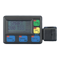
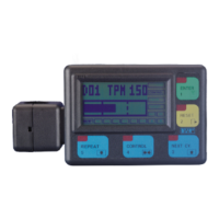
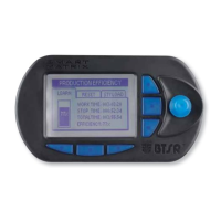
Details the control panel buttons and display zones of the SMART CLEARER system.
Describes the detection capabilities and characteristics of ISSC.. sensors.
Explains the real-time yarn control and defect detection functions of ISSC.. sensors.
Details the communication signals (input/output) of the ISSC.. sensors.
Explains the meaning of the green and red LEDs on the sensors.
Lists parameters influencing sensor defect detection and their ranges.
Steps to perform before initial system operation, including startup checks.
Outlines the main functions and their operational sequences within the system.
Covers initial system start-up and restarting after an alarm condition.
Steps for initial sensor setup and usage.
Procedure to resume operation after a fault.
Guide to accessing and navigating the main SETUP menu functions.
Steps for creating, modifying, and erasing articles.
Procedure for loading articles into sensor memory.
Method to read yarn diameter detected by sensors.
Explains the system's monitoring modes and fault counter display.
Lists common faults, their causes, and suggested solutions for the system.
Recommendations for routine cleaning and upkeep of sensors and the terminal.
Information regarding repair interventions and warranty validity.
Step-by-step guide for updating the terminal's software version.
Tables for noting down article settings to aid in creation and modification.
Flowchart for initial sensor numbering and configuration.
Flowchart for setting the sensor delay time before control status.
Flowchart for enabling/disabling the Touch Light button function.
Flowchart for configuring system operation modes.
Flowchart for configuring the ENABLE signal input.
Flowchart for configuring the STOP signal output.
Flowchart for configuring STOP signal output as continuous or pulse.
Flowchart for performing automatic or manual sensor calibration.
Flowchart for selecting sensor operating mode (Absolute or Relative).
Flowchart for setting a password to access menus.
Flowchart for reading and setting the printer's date and time.
Flowchart for testing communication between terminal and sensors.
Flowchart for testing the efficiency of the communication line.
Flowchart for checking sensor software versions and updating them.
Flowchart for creating new articles with quality control parameters.
Flowchart for modifying parameters of existing articles.
Flowchart for removing articles from the database.
Flowchart for loading articles into sensor memory.
Flowchart for unloading articles from sensor memory.
Flowchart for displaying articles currently loaded in sensors.
Flowchart for reading the yarn diameter detected by each sensor.
Shows a diagram illustrating the interconnection of devices in the SMART CLEARER system.
| Brand | btsr |
|---|---|
| Model | SMART CLEARER |
| Category | Control Systems |
| Language | English |