Technical Data and Installation
WINDINGFEEDER - 2.3 -
Input/output signals function
Inputs Function
P1P2
It causes a switching between P1 and P2 tensions (*)
The switch P2 → P1 only deletes the TARGET error.
RESET
This signal activation causes the alarms reset.
EXC
This signal activation causes a reset of the target internal counter.
Output Function
STOP1
It is activated when the Windingfeeder device generates an alarm.
STOP2
It is activated when the Windingfeeder device reaches the target.
(*) For more details about P1 e P2 tensions please refer to chapter 3 - Operation
Both: Inputs and Outputs can be programmed as normally open (NO) or normally closed (NC) contacts. The
programming is global, i.e. every input (and every output in the same way) operates as NO or NC, depending
on the selected option. For more details, please refer to chapter 3 – Operation – P4.7 SIGNAL POLARITY .
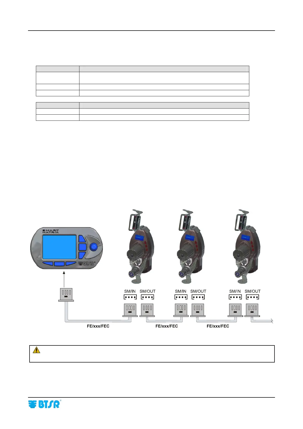
SMART MATRIX FEEDER – WINDINGFEEDER Connection
Concerning all electrical systems, it is a suggested rule to ensure that the ground cable
(GND) is connected to the device support.