PC ↔ SMART MATRIX ↔ SM-DIN Connection
SMART MATRIX - 1-1 -
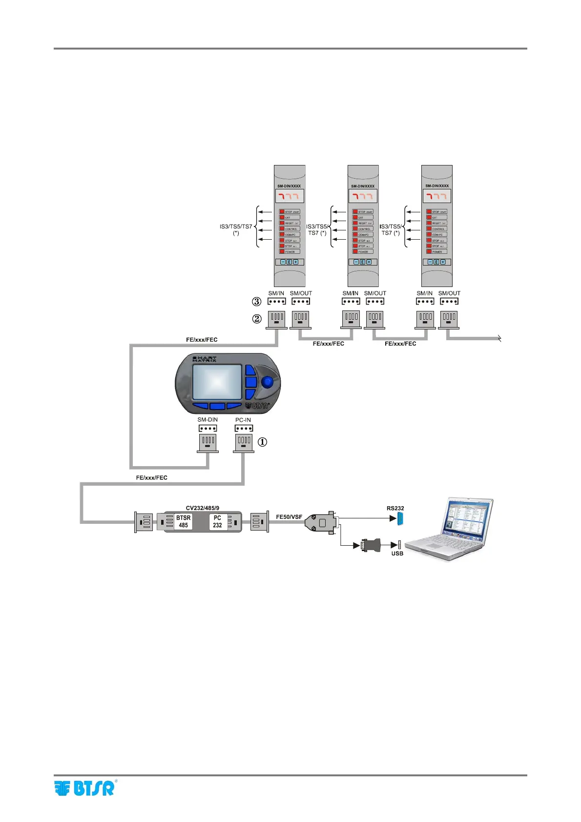
PC ↔ SMART MATRIX ↔ SM-DIN Connection
The following diagram shows the interconnections among: SMART MATRIX Terminal, SM-DIN Sensor
Interface Boards and PC.
The PC is mainly used for firmware update operations on SMART MATRIX Terminal, SM-DIN
Boards and Sensors (**).
(*) To connect the sensors, please refer to the following sections:
SMART MATRIX
↔
SM-DIN
↔
IS3/TS5/TS7 Sensors + ACT/Ds Connection.
(**) To update the firmware on SM-DIN Boards and Sensors, you must:
- Disconnect cable { from Smart Matrix PC-IN connector
- Disconnect cable | from 1
st
SM-DIN Board SM/IN } connector
- Connect cable { to connector } of 1
st
SM-DIN Board
Prior to operate the SMART MATRIX terminal, make sure you have programmed the communication
speed on all the SM-DIN WARP Boards as well as on CV232/485/9 module.
For more details, please refer to paragraph SMART MATRIX
↔
SM-DIN/PC Interface on Section 1
and to paragraph ID and Transmission Speed Configuration on Each SM-DIN Board on Section 3.
As alternative
Sensors
Sensors
Sensors