Sensors (ACT/Ds) Interface
SMART MATRIX - 1-6 -
Sensors (ACT/Ds) Interface
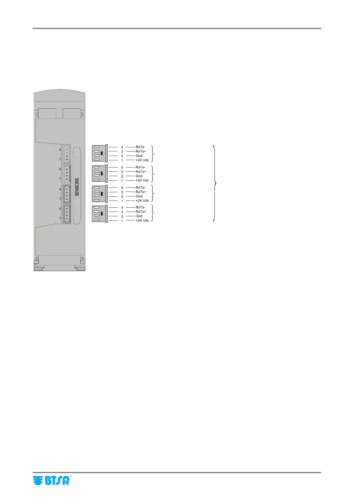
The following diagram shows the electrical interface (pin assignment) of SM-DIN to sensors connection.
As you may note, 4 identical connectors are available, allowing you to connect up to 4 sensors and/or
ACT/Ds chains.
The SM-DIN/WARP Board can directly supply up to 30 IS3 sensors or 20 TS5/TS7 sensors (I
max
=1A).
The ATC POWER unit must be used to supply a higher number of sensors. The unit is supplied by an
external power supplier (e.g. PSU 100ASM), as shown on the examples on pages 1-9 and 1-10.
Sensors (ACT/Ds)
Sensors (ACT/Ds)
Sensors (ACT/Ds)
Sensors (ACT/Ds)
Max 100 IS3 or
64 TS5/TS7 sensors
+
100 ACT/Ds modules
SM-DIN nn Module – (Identified by means of Edt function directly on the SM-DIN
module)