SM-DIN WARP
SMART MATRIX - 3-14 -
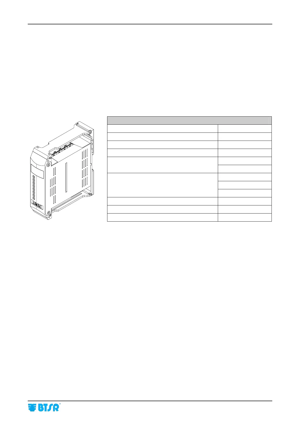
SM-DIN WARP
The SM-DIN WARP Boards represent the interface between Sensors/Lamps (ACT/D) and SMART MATRIX
Terminal.
For more details about the electrical interface, please refer to Section 1.
On each SM-DIN WARP Board it is necessary to setup 2 essential parameters:
P01 = Unique Board identification code (01 – 24)
P02 = Communication speed (Baudrate)
For more details, please refer to next page.
SM-DIN WARP Technical Characteristics
Power supply voltage 12-15 VAC / 24 VDC
Current absorption 200 mA Max
Protection fuse (Board protection) 5 A
Protection fuse (Sensor power supply) 3 A
0.3 A 125 VAC
Stop output (NO/NC)
1A 30 VDC
0 – 24 VDC
VIL Max 1.2 VDC
Inputs
VIH Min 5 VDC
Operating temperature range +10° / +60° C
Storage temperature range -25° / +85° C
Overall dimensions 138.5x124x35 mm