4
Tank Assembly
Logalux SM300/1 - SM400/1 - Technical specifications are subject to change without prior notice.
15
4.2 SM400/1 Placement and Installation
V Place tank shell in desired location.
V Slide insulation disc under tank between the tank sup-
ports.
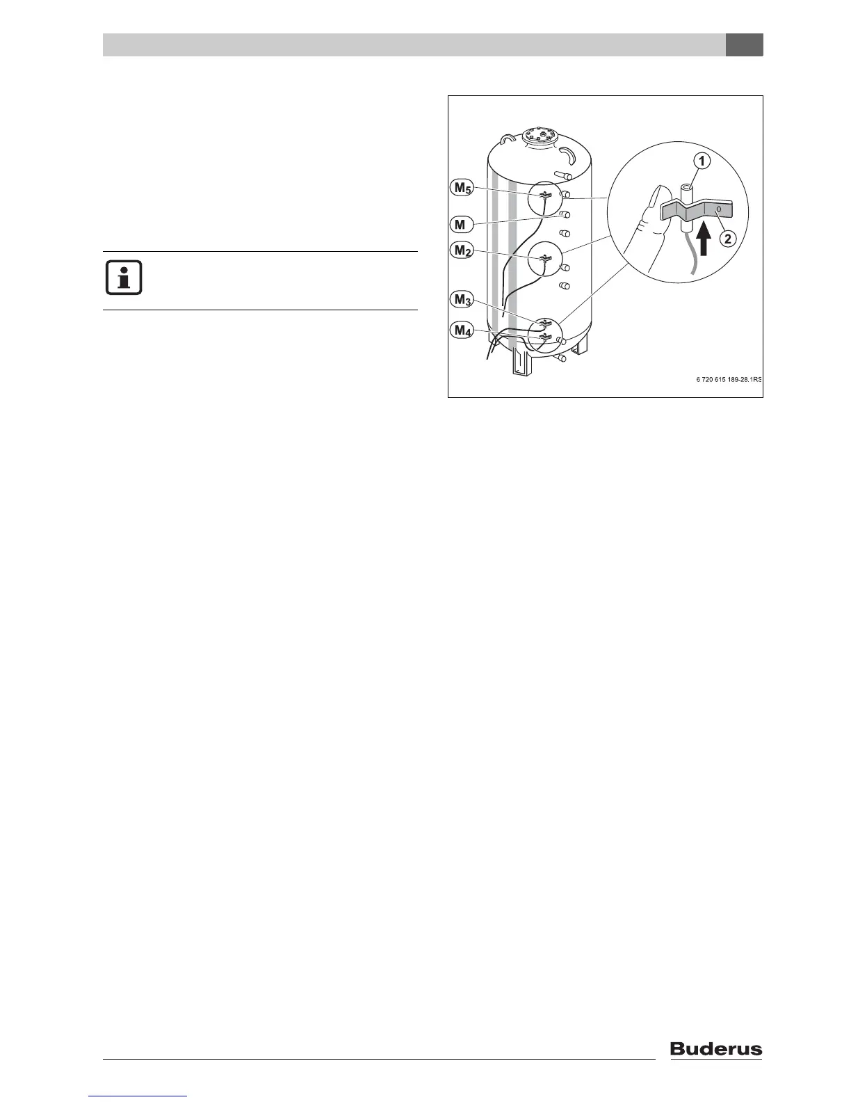
4.2.1 Installation of M2 - M5 temperature sensors
Alternatively to the sensor dry wells the M2 - M5 sensor
tension brackets can be used to install temperature sen-
sor on the outside of the DHK tank shell.
V Use heat conducting paste to improve contact.
V Slide sensor surface behind tension bracket to ensure
that the entire sensor surface is in contact with the tank
shell.
V Carefully route the sensor wiring.
V In order to install a well, remove the ½" cap (M) and
install a ½" dry well.
Fig. 13 Installation of temperature sensor
1 Temperature sensor
2 Tension bracket
M Dry well, for temperature sensor (FB) or Aquastat
M2 Alternative location for DHW temperature sensor (FB) or
shut-off sensor for loading by solid fuel boiler (FPU)
M3 Solid fuel boiler on temperature
M4 Temperature measuring point #2 for solar DHW sensor
(FSS)
M5 Temperature sensor location, to switch operation between
a solid fuel boiler and gas/oil boiler
Make sure to sensing elements are fully in-
serted into the wells and that they make good
surface contact.
 Loading...