Logamatic SC40 - Technical specifications are subject to change without prior notice.
43
Operation
5
5 Operation
V Hand all documents to the user.
V Explain to the user how the device works and how to operate it.
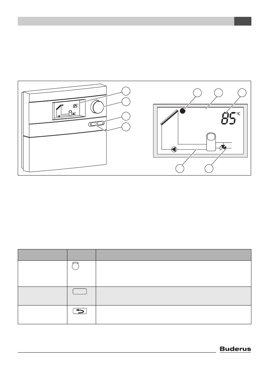
5.1 controller controls
Fig. 37 Controller and display
1 Display
2 Rotary selector
3 Back button
4 OK button
5 Symbol for temperature sensor
6 Displays of temperatures, hours of operation, etc.
7 Valve symbol (black = open outlet)
8 Active circulation diagram
Control Symbol Functions
Rotary selector – Selecting system settings (View level)
– Selecting function (Service level)
– Changing setting (Service level)
OK button – Opening submenu (Service level)
– Changing/saving setting (Service level)
Back button – Returning to higher menu level (Service level)
– Reverting to collector panel temperature display (View level)
Tab. 6
7747006072-23.1 SD
1
2
3
4
5 1 6
78
OK
 Loading...
