Logamatic SC40 - Technical specifications are subject to change without prior notice.
9
Installation (for engineers only)
4
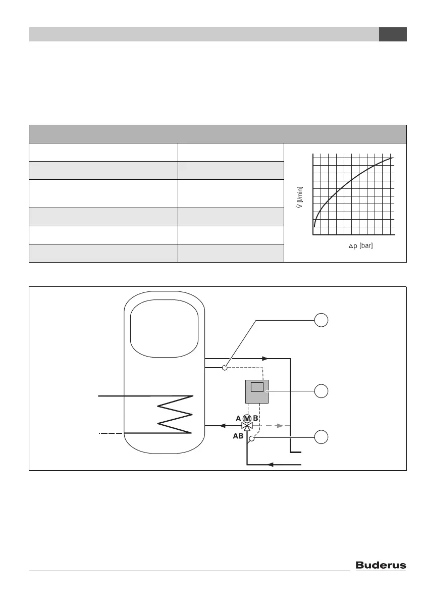
4.2 Installing diverter valve for return boost (optional)
The "return boost" function for boosting the heating system using the solar thermal system requires
a diverter valve to be fitted. The diverter valve directs the flow of central heating water either through
the thermal store or directly back to the boiler depending on the heating system's return tempera-
ture.
Fig. 4 Installation diagram for combination cylinder return boost
1 Cylinder temperature sensor S6
2 Solar thermal controller Logamatic SC40
3 Return temperature sensor S3
RL Heating return
RK Boiler return
Specifications of diverter valve
Max. closing pressure 0.55 bar (55 kPa)
Max. static pressure 8.6 bar (860 kPa)
Max. fluid temperature 95 °C, 110 °C for short
periods
kV rating 8.2
Voltage 230 V, 50 Hz
Maximum ambient temperature 50 °C
Tab. 3 Specifications and pressure loss characteristics of diverter valve
100
90
80
70
60
50
40
30
20
10
0,1 0,2 0,3 0,4 0,5
7747006072-03.1 SD
RK
RL
3
1
2
 Loading...
