Installation (for engineers only)
Logamatic SC40 - Technical specifications are subject to change without prior notice.
10
4
V Fit the diverter valve in the return pipe between the solar storage cylinder (Æ Fig. 4) and the
boiler.
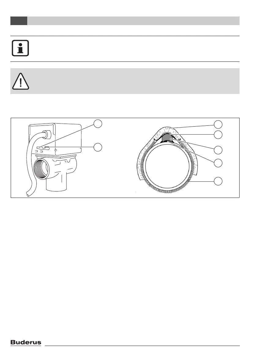
Fig. 5 Diverter valve (left) and fitted temperature sensor (right)
Function of valve switch
Use the "MAN" (manual, Æ Fig. 5, item 2) setting for filling, bleeding or draining the system or as
the safety setting when there is a power failure. In the "MAN" position, the valve actuator is in the
centre position. This allows even flow of the fluid through both outlet connections.
V For normal operation, set the switch to "AUTO" (Æ Fig. 5, item 1).
Installing the temperature sensors
There are 2 temperature sensors supplied with the valve. They can be used as cylinder temperature
sensors or pipe contact sensors (Æ Table 1, page 6).
V Apply heat conducting paste (Æ Fig. 5, item 6) to temperature sensor S3 (Æ Fig. 5, item 5).
V Fit temperature sensor S3 using retaining plate (Æ Fig. 5, item 4) and spring strap (Æ Fig. 5, item
7) to the return pipe approx. 20 cm upstream of the diverter valve.
V Provide temperature sensor S3 with insulation at least 20 cm long (Æ Fig. 5, item 3).
V Fit temperature sensor S6 in the position provided on the cylinder (see installation instructions
for cylinder).
Observe the connection markings on the diverter valve.The valve in Fig. 4 allows fluid
to flow from AB to B when de-energised. Once the set temperature difference is
reached, the valve switches over to divert the flow from AB to A.
Caution: Risk of system damage if the valve positioner casing is damaged.
V Use spanner on union nuts not on valve body.
7747004985.10-1.SD
2
1
3
5
6
7
4

 Loading...
