5
Installing the boiler
Logano G234X - Technical specifications are subject to change without prior notice.
25
In Canada the regulations in accordance with CAN/CSA
B 149.1 and 2 Installation Codes apply.
5.7.3 Installing the flue pipe
B Mount the flue pipe on the flue outlet of the draft hood.
B Mount the flue pipe (4) with corrosion-resistant sheet
metal screws.
5.7.4 Connecting flue pipe
Use only flue pipes with a suitable diameter for the boiler.
Every horizontal section of the flue pipe must have a
minimum rise of ¼ inches per foot (21 mm per m) towards
the chimney. The flue pipe must be securely fastened to
prevent it from hanging. A suspension must be installed at
least every 5 feet (1.5 m). Fasten every connection with at
least three (3) corrosion-resistance sheet metal screws.
The end section of the flue pipe must connect to the
inside of the chimney smoke duct.
A minimum clearance of 6 inches (155 mm) is required
between the flue pipes and all flammable materials.
The flue pipe must not be reduced in size and venting
must not be prevented by the installation of additional
components.
B Connect flue pipe to the chimney with the shortest
possible length of flue pipe.
5.7.5 Installation of vent damper
Only the vent damper supplied with the boiler must be
used for venting the boiler.
The position of the vent damper must be visible.
The back flow check must be at least 6 inches (155 mm)
from all flammable components.
The vent damper must be freely accessible for
maintenance.
The vent damper must be open when the main burner of
the boiler is operating.
B Place flue gas adapter [3] on the pipe nipples of the
draft diverter.
B Install pins in the hole of the vent baffle [1].
B Fasten flue baffle to the flue connector adapter with
three (3) corrosion-resistant self-tapping screws.
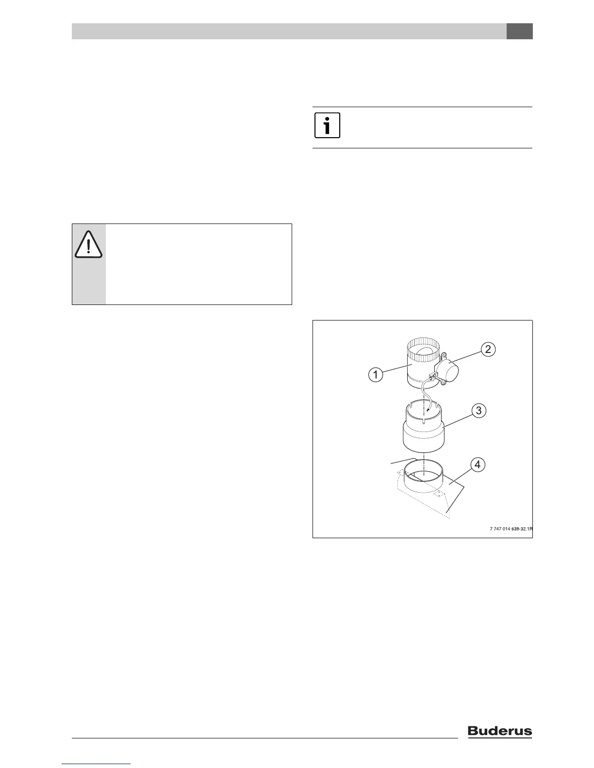
Fig. 26 Installation of vent damper
1 Vent Damper
2 Motor
3 Adapter for the flue outlet
4 Draft hood
G Any incorrect status of the common venting
system must be corrected to ensure that the
heating system complies with the regulations of
the National Fuel Gas Code, ANSI Z 223.1. If
the size of any component of the common
venting system is changed, the complete venting
system must be resized to comply with the
relevant tables in Part 11 of the National Fuel
Gas Code, ANSI Z 223.1.
DANGER: Risk of fatal injury from escaping
flue gases!
A draft hood that does not work properly can
cause dangerous flue gases to escape.
B Note that the draft hood check cannot be
modified.
In Canada the vent damper must not be
installed on a propane-fired heating system
with a electronic ignition system.

 Loading...