5. Press the CYCLE RUN Button. The Support Arm will begin to lower
and the Blade will rotate at the selected speed. The preset load will
not be applied for approximately 7 seconds. During this interval, the
sample will approach the blade and a 100g load will be applied in
order to establish a "kerf" cut. The unit will then apply the set load.
The ISOMET™ 2000 Saw is supplied with a 6″ dia. Wafering Blade
as standard equipment and the Support Arm is set at the factory to
accommodate this condition. In normal operation, the Arm auto-
matically advances the specimen into the Wafering Blade until the
cut is completed or until the lower position limit switch within the
cutter is activated, whichever comes first. If the specimen does not
contact the Wafering Blade within seven seconds, the Arm will
automatically return to the start position without cutting the sample.
This could occur if a much smaller Wafering Blade is used or if the
sample is very small and the Specimen Arm is not repositioned.
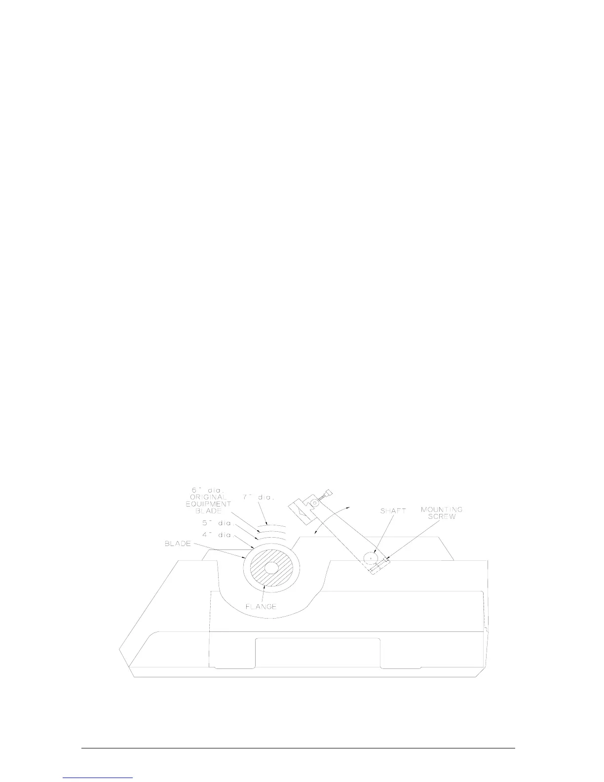
Figure 6 shows the factory set Arm position (when the arm is
raised to it’s maximum) relative to the various size Wafering
Blades that may be used with the ISOMET™ 2000 Saw. It is
easy to see that there is a considerable distance for the Support
Arm to travel before making contact with a four inch diameter
blade. The support arm should be lowered with the LOWER
button until the specimen is about 1 cm. from the blade before
starting the cut cycle.
If necessary to allow for a variety of operational conditions, the
Support Arm may be repositioned. This is accomplished by
loosening the Mounting Screw that secures the Support Arm to
the shaft. Be careful to prevent the Support Arm from striking
the Wafering Blade. Reposition the Support Arm as described in
Positioning The Sample section on page 6.
NOTE Do not move the specimen arm laterally along the shaft. The arm has
25.4 cm of stroke. Any loss in stroke by repositioning the arm may
result in the arm stalling against the cabinet resulting in loss of
micrometer accuracy.
Figure 6 Support Arm Adjustment
6. During operation, observe the Load Bar Graph. Due to
differences in sample thickness and density/consistency, or as
9
MA112480-20 03/06/00