19
Installation
Procedure for control function A
→ Pressurize lower control air connection with compressed air
(value as indicated on the type label) (see “Fig. 17”).
→ Place actuator on the body.
→ Lightly cross-tighten the body screws until the diaphragm is
between the body and actuator.
Do not tighten the screws yet.
→ Actuate the diaphragm valve twice to position the diaphragm
correctly.
→ Without applying pressure, tighten the body screws to the permitted
tightening torque (see “Tab. 7”).
→ Pressurize lower control air connection with compressed air (value
as indicated on the type label).
→ Check the tightening torque of the screws again.
Procedure for actuator with control functions B and I:
→ Place actuator on the body.
→ Lightly cross-tighten the body screws without pressurization until
the diaphragm is between the body and actuator.
Do not tighten the screws yet.
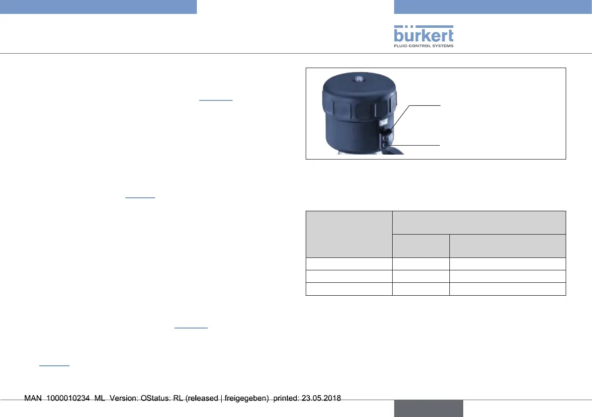
→ Pressurize upper control air connection with compressed air (value
as indicated on the type label) (see “Fig. 17”).
→ Actuate the diaphragm valve twice.
→ Tighten the body screws to the permitted tightening torque (see
“Tab. 7”)
Upper control air connection
(for CFB and CFI)
Lower control air connection
(for SFA and SFI)
Fig. 17: Control air connection
Tightening torques for plastic body, VA tubular body (VA) and
forged body
Orifice
(Diaphragm size)
DN [mm]
Tightening torque [Nm]
(values for guidance)
EPDM/FKM PTFE / advanced PTFE /
laminated advanced PTFE
65 20 30
80 30 40
100 40 50
Tab. 7: Tightening torques for diaphragms
english
Type 2030, 2031, 2031 K, 2032,
2033, 2037