6 | Electrical Connection
24 | 52 Instruction Manual COBRA NC 2500 B WCV_EN_en
6.4 Electrical Connection of the Monitoring Devices
WARNING
If the monitoring sensors are not used.
Risk of explosion!
● Always use the mandatory monitoring sensors.
WARNING
Another sensor type.
Risk of severe injury!
Risk of explosion!
● Only the following sensor type(s) has (have) been approved by Busch and it (they) cannot be re-
placed by another one without authorization of the Busch representative.
NOTE
In order to prevent potential nuisance alarms, Busch recommends that the control system is
configured with a time delay of at least 20 seconds.
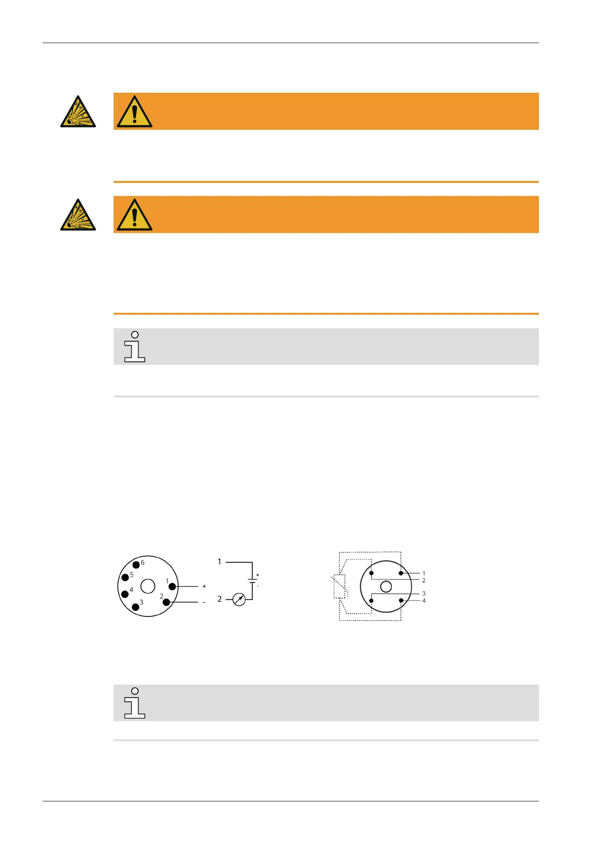
6.4.1 Wiring Diagram Resistance Thermometer
Part no.: PT100: 0651 550436 / Transmitter: 0643 536800
U
i
=30VDC; I
i
=100mA; P
i
=750mW; L
i
=0µH; C
i
=0pF
4 ... 20 mA ► 0 ... 300 °C
Maintenance procedure: Resistance Thermometer Calibration [➔38]
Trip signal (Cooling liquid / TSA1): T
trip
: 70 °C
Trip signal (Exhaust gas / TSA2): T
trip
: 245 °C
Wiring with transmitter:
1 = Brown ; 2 = Blue
Wiring without transmitter:
1 and 2 = Red ; 3 and 4 = White
6.4.2 Wiring Diagram Vibration Diagnostic Unit
NOTE
The wiring diagram is separately provided (specific sheet) with the machine.