© Alamo Group.Inc.
RTG SERIES TILLER 05/16 Assembly Section 3-10
ASSEMBLY
ASSEMBLY
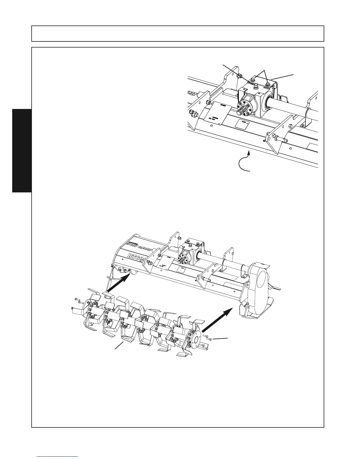
Step 8. Place the Gearbox on the mainframe with the
Vent plug on top. Move the Gearbox in place,
aligning the Hex Shaft and the Tube through the
Gearbox. Align the four holes in the mainframe
with the Gearbox mounting holes and reinstall
the four 1/2” x 1-3/4” bolts and lockwashers pre-
viously removed from this location.
Reattach the Gearbox Mounting Plate to the
Gearbox with the two 1/2” x 1-1/4” bolts, lock-
washers and flatwashers previously removed.
Gearbox
Mounting
Plate
1/2” x 1-1/4” Bolts
Lockwashers
Flatwashers
1/2” x 1-3/4” Bolts
Lockwashers
Located on the underside
Vent Plug
Step 9. Turn the Tine Bar 180 degrees from the original position when removed. Reattach the Tine Bar As-
sembly to the Tiller using the eight 1/2” x 1-3/4” bolts, lockwashers and hex nuts.
(Note : If the fasteners are damage or worn from previous usage replace them.)
With the Tine Bar assembly in place, at ground level , the cutting edge of the tines should be toward
the front (facing forward).
Cutting Edge
Facing Forward
1/2” x 1-3/4” Bolts
Lockwashers
Hex Nuts
(4) Per Side