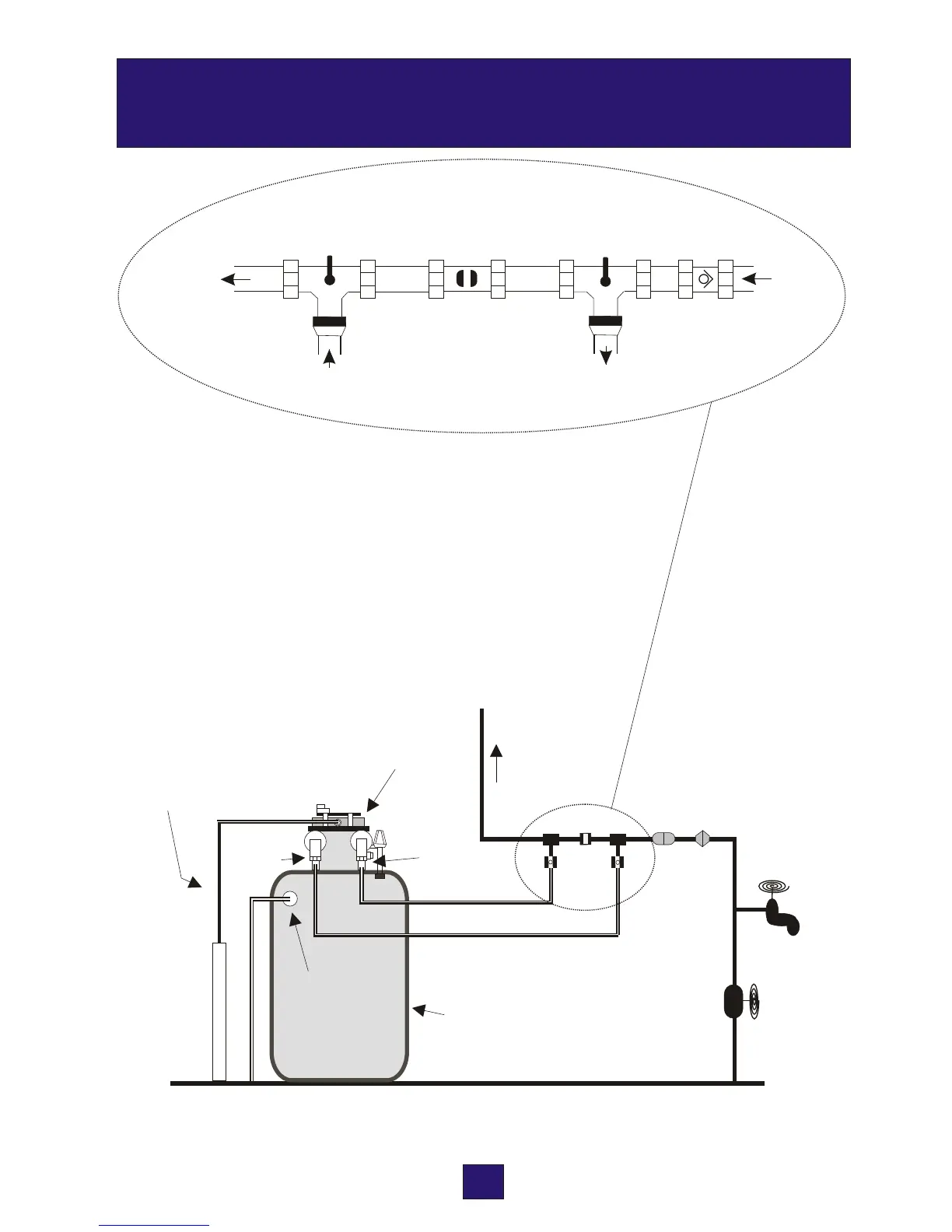
Key to the diagram
A. Non return valve
B. Pressure reducing valve (where required)
C. Inlet valve
D. Bypass valve
E. Outlet valve
6
N
P
A
R
T
O
E
A
B
C
E
D
Mains stop valve
Drinking
water
Drain hose
Overflow*
Valve Head
Brine
Cabinet
Inlet
Outlet
Rising Main
* The overflow must discharge to a place that is visable outside the building.
INSTALLATION LAYOUT
7
PART TWO
INSTALLING YOUR WATER SOFTENER
It is very important to establish the water pressure before installing the water softener. If
the water pressure is low then the water softener may not operate effectively. If it is too
high, then components inside the unit may be damaged.
Water pressure should be tested with a gauge at the kitchen tap or outside tap.
It should be noted that water pressure can increase at periods of low water usage e.g.
overnight. If therefore, the daytime pressure exceeds 5 BAR or if you are unsure
about pressure, then a pressure-limiting valve should be fitted.
Where the pressure is less than 1.7 BAR a booster pump may be required.
2. Inlet and outlet connections
1. Positioning the water softener
With the bypass valve open and the inlet / outlet valves closed the unit can be connected
to the plumbing system. Arrows on the inlet and outlet piping from the valve will confirm
the direction of flow.
Connections can be made in one of three ways - where high flow rates are not required
(static head systems) these connections can be made using the standard flexible hoses
supplied with your softener, ensure the hoses are not kinked as this may restrict flow. For
systems requiring higher flow rates (those fitted with combination boilers or unvented
pressurised systems) the connections should be made using specialist high flow hoses
supplied with a HI-FLO softener, or conventional copper tube and fittings.
3. Drain connection
Push the flexible drain hose onto the barbed connector (Drain) as shown on page 6 and
secure with the clip provided. Run the drain hose to a stand pipe or to a drain. The air gap
needs to be at least 20mm . Softened water will have no adverse effect on a septic tank.
You can extend the drain up to 9m if you have sufficient pressure (greater than 3 BAR).
The drain hose must not be kinked or restricted in any way as this will cause an overflow
from the brine cabinet.
Frost protection
o
If the drain hose or connecting pipework is likely to be subject to temperatures below 0 C it
must be protected to prevent freezing. Failure to observe this precaution could lead to the
water softener overflowing.
Raising the drain hose
If you have a water pressure of 3 BAR or more, you can raise the drain to a maximum of 3
metres above the valve head.
P
A
T T
W
O
R
Outlet valve
shown open
By-pass valve
shown closed
Inlet valve
shown open
Outlet from
softener
Inlet to
softener
Inlet from
mains
Non-return
valve
To rising
main