English
29
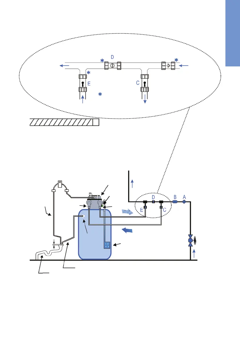
3.4 Installation Layout
Inlet from
mains
1
Non-return valve
inlet valve
shown open
Inlet to
softener
1
By-pass valve
shown closed
use reducing bush
for 15 mm
pipework
Outlet from
softener
Outlet valve
shown open
to rising
main
2
1
Inlet water = Hard water = drinking water
2
Outlet for soft water
Key to the diagram:
A. Non-return valve
B. Pressure reducing valve (when required)
C. Inlet valve (hard water) ¾“
D. Bypass valve
E. Outlet valve (soft water) ¾“
F. Mains stop valve
G. Brine storage cabinet
Key to the diagram (continued):
H.
I.
Waste water hose
J.
K. Flexible hose, overflow
L.
Control valve (green)
M. Servo-motor for valve positioning
N. Distance device & ceiling of room
O. Overflow connection ½“
P.
Fixing clop for flexible hose
Connection to drain
Hose barb (waste water trap)
L
Valve head
I
J. Drainage
(Existing or new ‘entrapped‘ stand pipe or to external drainage)
K
L
G
F
H
P
Rising main
C
E
M
20 mm
N
Observe a miminum distance to the ceiling (N) of 0.5 m.