81
Nederlands
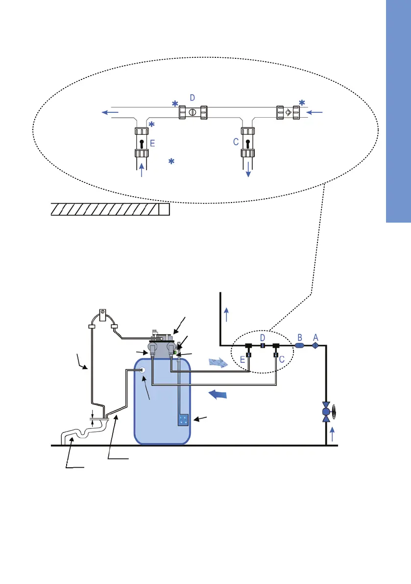
3.4 Installatieschema
Netingang
1
Terugslagklep
Inlaatventiel
open
Inlaat van de ontharder
1
Bypass ventiel gesloten
Gebruik een
reductiebus voor
15 mm leidingen
Uitgang van de
ontharder
Uitlaatventiel open
Voor de
hoofdleiding
2
1
Ingangswater = Hard water = drinkwater
2
Uitgang voor onthard zacht water
Legende voor de installatie::
A. Terugslagklep
B. Drukverminderingsventiel (wanneer noodzakelijk)
C. Inlaatventiel (hard water) ¾“
D. Bypass ventiel
E. Uitlaatventiel (zacht water) ¾“
F. Hoofdafsluitventiel
G. Voorraadreservoir voor zout
Legende voor de installatie (vervolgd):
H.
I.
Afvalwaterslang
J.
K. Flexibele slang, overloop
L.
Regelventiel (groen)
M. Servomotor voor ventielpositionering
N. Afstandhouder & kamerplafond
O. Overloopbuis ½“
P.
Bevestigingsklem voor de flexibele slang
Aansluiting voor afvoer
Slangbuis (externe afvoer)
L
Drukventielkop
I
J. Afvoer (*Bestaand of nieuwe „ingesloten” standbuis voor de externe uitlaat van het afvalwater)
K
L
G
F
H
P
Hoofdwaterleiding
C
E
M
20 mm
N
Let op een maximale afstand tot het plafond van het gebouw (N) van 0,5 m.