Lightning Series Fiber Laser User Manual
8
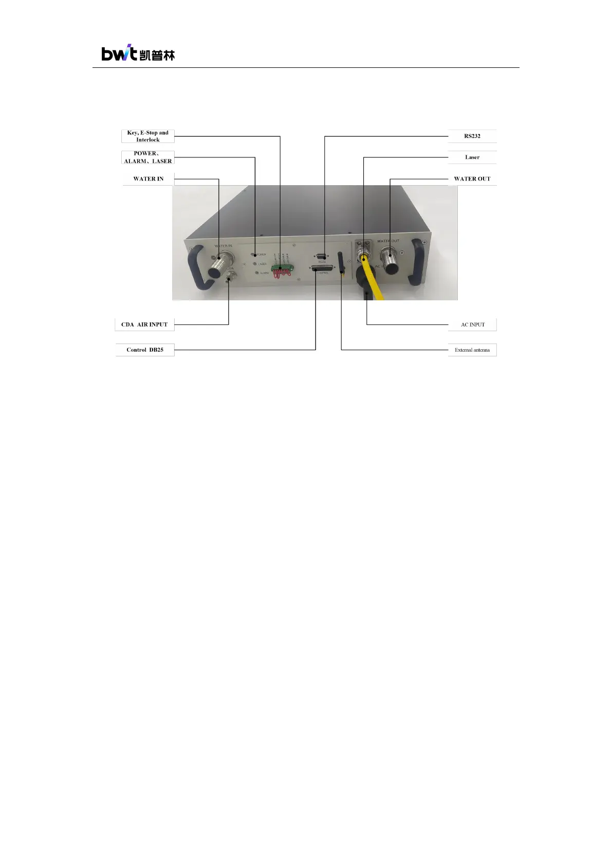
The laser panel and definition description are shown in the figure below.
Figure 2 Laser Rear Panel Instructions
1) WATER IN and WATER OUT are the cooling water inlet and outlet of the laser. Refer
4.4 Cooling System Requirements for details.
2) AC INPUT is the AC 220V/380V voltage input interface, please refer to the power
supply requirements in 3.3 Product Specifications for details.
3) Power-on indicator (POWER): After powering on, this indicator flashes. The indicator
will light up with no flash when the laser is ready. The indicator will light off when there
is some fault.
4) Alarm indicator (ALARM): When there is some fault, the alarm indicator lights up.
5) Laser indicator (LASER): This indicator lights up when the laser beam is output, and
lights off when the laser beam output is shut down.
6) Control interface (CONTROL): This is a DB25 interface. The external signal control
board can be connected to the laser through this interface for laser external control and
operation.
7) Communication interface (RS232): This is a DB9 interface. The computer with
operating software can be connected to the laser through this interface to for laser
internal control, operation and status check.
8) Key, emergency stop and interlock ports: PIN1~PIN2 are connected to the key switch,