Lightning Series Fiber Laser User Manual
9
PIN3~PIN4 are connected to the emergency stop button, PIN5~PIN6 are connected to
the water cooling interlock, and PIN7~PIN8 are connected to the safety interlock which
is used for the connection and control of external switch interlock.
9) Laser output (LASER): fiber armored cable for laser output.
10) CDA: clean and dry air port. CDA supply (0.1MPa, free of moisture and oil) is
connected to this port to prevent laser from condensation.
11) External antenna for Bluetooth connection.
3.6. Definition of Control Interface
Control mode: As the rear panel shown in Figure 2, Lightning Series fiber laser include
RS-232 communication interface, DB25 control interface and switch interlock interface.
1) The definitions of RS-232 communication interface are shown in Table 4:
Table 4 RS-232 Communication Interface Definition
RS-232 communication reception
RS-232 communication sending
RS-232 communication ground
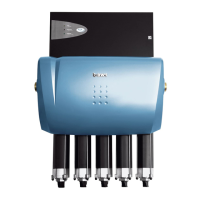
Figure 3 RS-232 PC operation software
2) The specific parameter requirements of the communication control interface are shown
in Table 5: